
Suppose, there is a three-phase network.
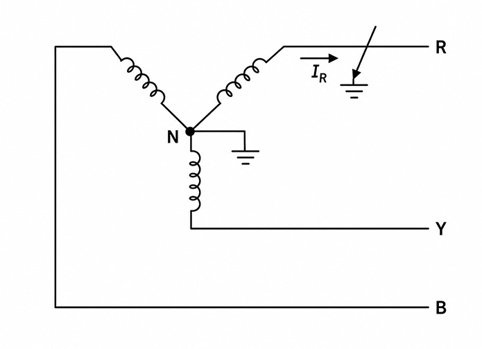
An earth fault occurs at the red phase. For that fault, let us say current \(I_R\) starts flowing. Since this is an asymmetrical fault, there will be positive, negative and zero sequence currents in the system.
Also, let us consider that at the instant of the fault there was no current flowing in the network. Actually, at the instant of the fault, normal load current was flowing through all three phases of the network, but as this normal current does not come under fault analysis, we have considered the system was unloaded at the instant of the fault.
Now, say the positive sequence, negative sequence and zero sequence currents of the system due to that asymmetrical fault are \(I_1\), \(I_2\) and \(I_0\), respectively.
Now we can represent the currents of the network at the instant of fault with a operators as:
\[\begin{bmatrix}I_R\\I_Y\\I_B\end{bmatrix}=\begin{bmatrix}1&1&1\\1&a^2&a\\1&a&a^2\end{bmatrix}\begin{bmatrix}
I_0\\I_1\\I_2\end{bmatrix}\]
Which we can also write as:\[\begin{bmatrix}I_0\\I_1\\I_2\end{bmatrix}=\frac{1}{3}\begin{bmatrix}1&1&1\\1&a&a^2\\1&a^2&a\end{bmatrix}\begin{bmatrix}I_R\\I_Y\\I_B\end{bmatrix}\]
Now, for a single phase-to-earth fault, currents through the other phases are zero. Since we have considered that at the instant of the fault, the system was unloaded, ultimately we can write:\\begin{bmatrix}I_0\\I_1\\I_2\end{bmatrix}=\frac{1}{3}\begin{bmatrix}1&1&1\\1&a&a^2\\1&a^2&a\end{bmatrix}\begin{bmatrix}I_R\\0\\0\end{bmatrix}\]Therefore, we can write
\[I_0=\frac{1}{3}I_R+\frac{1}{3}\times0+\frac{1}{3}\times0\]\[I_0=\frac{1}{3}I_R\]Similarly,\[I_1=\frac{1}{3}I_R+\frac{1}{3}\times0\times a+\frac{1}{3}\times0\times a^2\]\[I_1=\frac{1}{3}I_R\]\[I_2=\frac{1}{3}I_R+\frac{1}{3}\times0\times a^2+
\frac{1}{3}\times0\times a\]\[I_2=\frac{1}{3}I_R\]Therefore,\[\boxed{I_0=I_1=I_2=\frac{I_R}{3}}\]
Equivalent Sequence Circuit of the Fault Condition
All sequence currents are the same. Hence, all the sequence reactance will be in series. This is because the same current is flowing through these reactance. So we can draw:
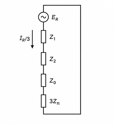
Sequence network:
- Positive-sequence impedance: \(Z_1\)
- Negative-sequence impedance: \(Z_2\)
- Zero-sequence impedance: \(Z_0)
- Neutral impedance contribution: \(3Z_n\)
The zero-sequence current \(3I_0\) will flow through that neutral path. Therefore, the total voltage drop in this path will be:\[3Z_n I_0\]In respect of a single \(I_0\), we can assume the impedance of the neutral-to-fault path is:\[3Z_n\]
Here, \(E_R\) is the EMF of the red-phase source. \(Z_1\) and \(Z_2\) are the positive- and negative-sequence impedances of the network. Therefore,\[I_1=I_2=I_0\frac{E_R}{Z_1+Z_2+Z_0+3Z_n}\]Thus, for a single line-to-ground fault, the positive-, negative-, and zero-sequence networks are connected in series. The sequence current is:\[\boxed{
I_0=I_1=I_2=\frac{E_R}{Z_1+Z_2+Z_0+3Z_n}}\]The corresponding fault current in the red phase is:\[I_R=I_0+I_1+I_2\]Since,\[
I_0=I_1=I_2\]we get\[I_R=3I_0\]or\[\boxed{I_R=\frac{3E_R}{Z_1+Z_2+Z_0+3Z_n}}\]