What is corona?
At very high voltage condition of a transmission conductor, the voltage gradient distribution of the conductor from its surface along the distance in the air is not linear. Rather, it is very high at the surface of the conductor then it decreases along the distance in air gradually but not linearly. If we draw a graph against the voltage gradient or electric field strength against distance, we shall get a curve like shown below.
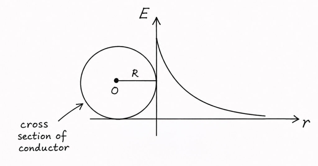
As the voltage gradient is very high at the surface, the electric field strength at most surface around the conductor surface will be so high that, it can cause the ionization of air at this space. This ionized air becomes conducting hence causes localized discharge of charge in the air.
This discharge causes visible bluish glow accompanied by hissing sound in the air surrounding the conductor. This phenomenon is commonly known as corona.
Critical Disruptive Voltage for Corona
The critical disruptive voltage is the voltage above which disruptive of air dielectric occurs. In other words, the voltage corresponds to the gradient at the surface of the conductor equals to the breakdown voltage of air.
Now, we shall try to calculate the critical disruptive voltage for corona. Suppose there are two parallel conductors. One contains charge per unit length. Other contains negative charge for the same unit length. is the distance between the conductors.
Parallel Conductors
Let us name one conductor with letter A and other with letter B. A contains charge and B contains charge. is the radius of both conductors. Let us consider a point between the conductors at a distance from the central axis of the conductor A.
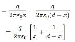
Therefore, the distance of the point from the central axis of the conductor B is . Now, obviously the electric field strength at point due to conductor A is
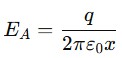
and that will be directed from conductor A to B. On the other side, the electric field strength at point due to conductor B is
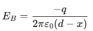
The negative sign is for negative charge of conductor B. Also, this sign indicates that the field is also from A to B. Therefore, resultant electric field at point is

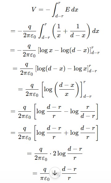
The potential difference between the conductors,
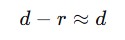
Now, is very very large compared to radius of the conductors. Therefore, we can say,
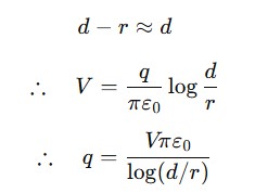
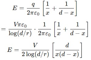
Electric field at point can be written as
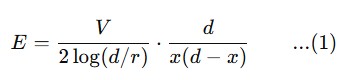
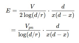
As we have considered conductor A contains positive charge and conductor B contains negative charge of same value, the midpoint of these two conductors is obviously the neutral zone. So, if we consider the line to neutral voltage in that case, that can be written as V/2. Say this is . So, we can write the equation (1) as
Now, the field intensity is maximum at the surface of the conductor. Hence we can write
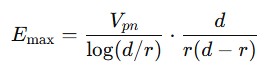
Since ,
Therefore,
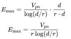
Hence,
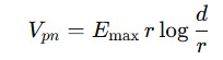
Now, in three phase system,
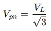
Where, is the line-to-line voltage, like 220 kV, 400 kV etc.
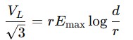
The dielectric strength of air means the maximum field that the air can withstand is or . So, we can write,
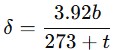
This voltage means line voltage above which corona starts. The above equation is an approximation considering the air breakdown voltage gradient as . As per standard, this value is taken in respect of ambient and of Hg pressure. But if we consider actual condition of air, we can write,
where,
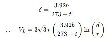
Where is the barometric pressure in mm of Hg and is the temperature in . This critical disruptive voltage is derived considering the surface of the circular cross-sectional conductor is smooth. But in actual stranded conductor, the surface of the overall conductor is not smooth. Rather, the periphery of the cross-section is the series of arcs of circular strands of much smaller diameter than the overall conductor. Because of this, the breakdown voltage calculated or derived will be somewhat smaller than that of a solid round conductor.
That is why a factor called irregularity factor is multiplied with the calculated critical disruptive voltage. The disruptive voltage of a smooth round conductor of equivalent diameter of the stranded conductor. For ACSR conductors, we normally consider it as .
So, the critical disruptive voltage for ACSR or other stranded conductors becomes
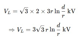
Visible Disruptive Voltage
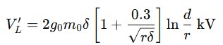
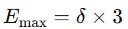
The voltage we have derived is not the voltage at which visible corona starts. During this, corona starts at the calculated voltage. But the voltage at which visible bluish corona starts with hissing sound, that voltage is expressed as,
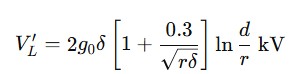
Here, is the air breakdown voltage which we have taken as 3 kV/mm.
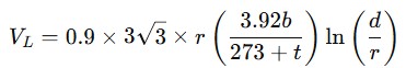
is the air density factor which we have derived and written as above. Now we include the irregularity factor m0, that we have already considered as mo = 0.9, for stranded conductors. So,