Inductance of a Transmission Line – Complete Derivation

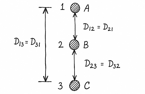
We mark the conductors as A, B, and C. Additionally, we mark the position of the conductors in the transmission line as 1, 2, and 3. The distance between conductors A and B is D12D_{12}​. Similarly, we can say, the distance between conductors B and A is D21D_{21}.

Inductance of a Transmission Line

Therefore,D12=D21D_{12}=D_{21}Similarly, the distance of conductor B to C and C to B are D23D_{23}​ and D32D_{32},​ respectively. Hence,
D23=D32D_{23}=D_{32}Lastly, the distance of conductor C to A and A to C are D13D_{13}​ and D31D_{31}, respectively. Therefore,
D13=D31D_{13}=D_{31}

Fictitious Radius of a Conductor

Also consider the radius of the conductors is r. Therefore, the fictitious radius will be,
r=r×0.7788r’ = r \times 0.7788

Balanced Currents

Also, we assume that conductors A, B, and C are carrying current I1I_1​, I2I_2​ and I3I_3​. As it is a three-phase balanced system, we know thatI1+I2+I3=0I_1+I_2+I_3=0

Flux Linkage of Conductors

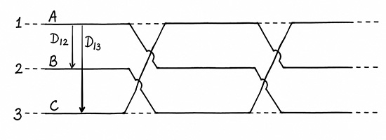
Now, the flux linkage of conductor A for its own current and the currents on the other two conductors isλA=2×10⁷[I1ln1r+I2ln1D12+I3ln1D13]\lambda_A = 2\times10^{-7} \left[ I_1\ln\frac{1}{r’} + I_2\ln\frac{1}{D_{12}} + I_3\ln\frac{1}{D_{13}} \right]Now, along the length of this transmission line, the conductors are transposed at two intermediate points.

For section – 1, the flux linkage will be represented asλA1=2×10⁷[I1ln1r+I2ln1D12+I3ln1D13]\lambda_{A1} = 2\times10^{-7} \left[ I_1\ln\frac{1}{r’} + I_2\ln\frac{1}{D_{12}} + I_3\ln\frac{1}{D_{13}} \right]

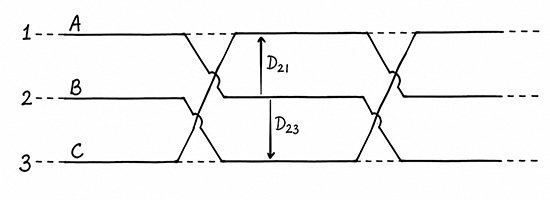
Obviously, for section – 2, the flux linkage of conductor A for its own current and the current of other conductors will be,λA2=2×10⁷[I1ln1r+I2ln1D23+I3ln1D21]\lambda_{A2} = 2\times10^{-7} \left[ I_1\ln\frac{1}{r’} + I_2\ln\frac{1}{D_{23}} + I_3\ln\frac{1}{D_{21}} \right]

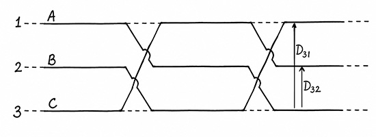
Similarly, for section – 3, the flux linkage of conductor A for its own current and the current of other conductors will be,λA3=2×10⁷[I1ln1r+I2ln1D31+I3ln1D32]\lambda_{A3} = 2\times10^{-7} \left[ I_1\ln\frac{1}{r’} + I_2\ln\frac{1}{D_{31}} + I_3\ln\frac{1}{D_{32}} \right]

Video on Inductance of Three Phase Transmission Line

Average Flux Linkage

Therefore, the average flux linkage of conductor A will beλA=λA1+λA2+λA33\lambda_A = \frac{\lambda_{A1}+\lambda_{A2}+\lambda_{A3}}{3}=2×1073[3I1ln1r+I2(ln1D12+ln1D23+ln1D31)= \frac{2\times10^{-7}}{3} \Bigg[ 3I_1\ln\frac{1}{r’} + I_2\left( \ln\frac{1}{D_{12}} +\ln\frac{1}{D_{23}} +\ln\frac{1}{D_{31}} \right)+I3(ln1D13+ln1D21+ln1D32)]+ I_3\left( \ln\frac{1}{D_{13}} +\ln\frac{1}{D_{21}} +\ln\frac{1}{D_{32}} \right) \Bigg] =2×10⁷[I1ln1r+I2ln1D12D23D313+I3ln1D13D21D323]= 2\times10^{-7} \left[ I_1\ln\frac{1}{r’} + I_2\ln\frac{1}{\sqrt[3]{D_{12}D_{23}D_{31}}} + I_3\ln\frac{1}{\sqrt[3]{D_{13}D_{21}D_{32}}} \right]

Again,D12D23D313=D13D21D323=Deq\sqrt[3]{D_{12}D_{23}D_{31}} = \sqrt[3]{D_{13}D_{21}D_{32}} = D_{eq}Therefore,λA=2×10⁷[I1ln1r+I2ln1Deq+I3ln1Deq]\lambda_A = 2\times10^{-7} \left[ I_1\ln\frac{1}{r’} + I_2\ln\frac{1}{D_{eq}} + I_3\ln\frac{1}{D_{eq}} \right]=2×10⁷[I1ln1r+(I2+I3)ln1Deq]= 2\times10^{-7} \left[ I_1\ln\frac{1}{r’} + (I_2+I_3)\ln\frac{1}{D_{eq}} \right]Since,I1+I2+I3=0I_1+I_2+I_3=0I2+I3=I1I_2+I_3=-I_1Hence,λA=2×10⁷[I1ln1rI1ln1Deq]\lambda_A = 2\times10^{-7} \left[ I_1\ln\frac{1}{r’} – I_1\ln\frac{1}{D_{eq}} \right]=2×10⁷I1ln(Deqr)= 2\times10^{-7}I_1 \ln\left(\frac{D_{eq}}{r’}\right)Therefore, the inductance of the conductor A is,LA=λAI1=2×10⁷ln(Deqr)H/mL_A=\frac{\lambda_A}{I_1} = 2\times10^{-7} \ln\left(\frac{D_{eq}}{r’}\right) \quad \text{H/m}

Special Case: Vertical Conductor Configuration

If the spacing between adjacent conductors is h, D12=D21=D23=D32=hD_{12}=D_{21}=D_{23}=D_{32}=hAlso, the distance between the top and bottom conductors isD13=D31=2hD_{13}=D_{31}=2hTherefore,Deq=D12D23D133=2h33=23hD_{eq} = \sqrt[3]{D_{12}D_{23}D_{13}} = \sqrt[3]{2h^3} = \sqrt[3]{2}\,hSubstituting into the inductance expression,LA=2×10⁷ln(23h0.7788r)L_A = 2\times10^{-7} \ln\left(\frac{\sqrt[3]{2}\,h}{0.7788\,r}\right)​Since,230.7788=1.6177\frac{\sqrt[3]{2}}{0.7788}=1.6177The final expression becomesLA=2×10⁷ln(1.6177hr) H/m\boxed{ L_A = 2\times10^{-7} \ln\left(1.6177\frac{h}{r}\right) \ \text{H/m} }

Numerical Example of Inductance of a Transmission Line Conductor

Suppose, the clearance between adjacent conductors is h=3mh=3\,mThe conductor is ACSR Panther hence, the conductor diameterd=21mm=0.021md=21\,mm=0.021\,mHence,r=0.0212=0.0105mr=\frac{0.021}{2}=0.0105\,mSubstituting,L=2×10⁷ln(1.6177×30.0105)L = 2\times10^{-7} \ln \left( 1.6177\times\frac{3}{0.0105} \right)=2×10⁷ln(462.2)= 2\times10^{-7} \ln(462.2)=2×107×6.136= 2\times10^{-7}\times6.136L=1.227×10⁶  H/m\boxed{ L = 1.227\times10^{-6}\;H/m }orL=1.227  mH/km\boxed{ L = 1.227\;mH/km }

Video on Inductance of Three Phase Transmission Line