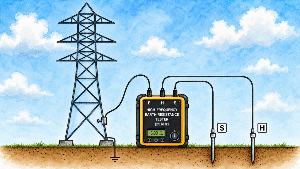
Generally, we measure grounding resistance using the three electrode method. In this method, we inject a high frequency current, typically around 25 kHz, into the soil and measure the potential drop along the line of measurement using a potential probe inserted between the earth electrode and the current probe.
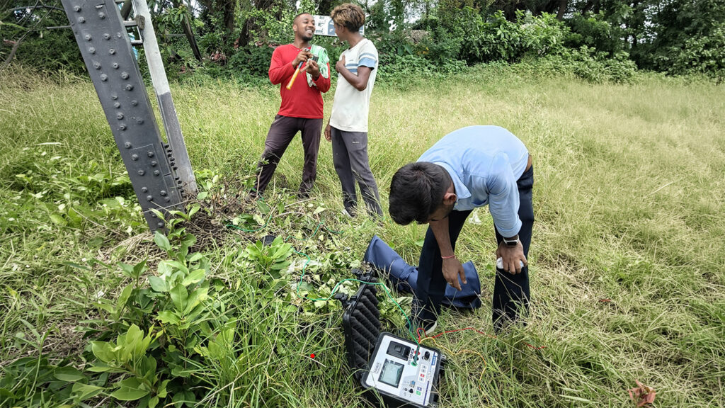
For power transmission tower footing resistance measurement purpose, we place the earth resistance measuring instrument near the tower footing. Then we connect the common terminal (E), to the tower leg. Next, we insert the current probe terminal (H) at a specified distance from the tower. Generally, the instrument manufacturer, recommends this distance. Obviously, this current probe probe injects current into the soil. Then, we insert the potential probe terminal (S), approximately midway between the E and H. This potential probe measures the potential drop in the soil along the same line.
By dividing the measured potential drop by the injected current, we obtain the impedance of the grounding path. Accordingly, the instrument calculates the earth impedance of the tower.
Actually, a tower is part of a transmission line. So, the overhead earth wire connects to all the towers of the line. Therefore, all the towers get earth connection through the earth wire. Therefore, there will be numbers of parallel path to the earth on both sides of the tower under test. So, if we now measure the earth resistance using the conventional low frequency method, a significant error occurs. Because the tower under test is also connected to the earth through the grounding systems of adjacent towers. To overcome this problem, we use the high-frequency measurement method.
Basic Principle of High Frequency Tower Footing Resistance Measurement
The basic principle of High Frequency Tower Footing Resistance Measurement is quite simple. Here, we inject a current with a frequency of at least 25 kHz. This frequency is generally sufficient to minimize the effect of adjacent towers.
The 25 kHz current also attempts to flow through the overhead earth wire toward the neighboring towers. However, at such a high frequency, the inductive reactance of the overhead earth wire becomes significantly high. As a result, the impedance of that path increases considerably. In other words, from the perspective of the test current, the adjacent towers on both sides appear to be disconnected. Therefore, the influence of the neighboring towers is effectively nullified by the high-frequency current. This is the basic principle of high frequency tower footing resistance measurement method.
Prediction of Resistance
The injected current consists a high-frequency. Therefore, the measured value initially represents the impedance of the earth path of the tower legs at 25 kHz rather than its pure resistance.
The instrument then analyzes the capacitive and inductive effects present in the system. Based on this analysis, it calculates the actual earth resistance and displays various parameters. The parameters include the resistance of the earth path, its inductive component, its capacitive component, and the total impedance of the tower grounding system.
Obtaining the More Accurate Value
During the measurement, we also move the voltage probe to several different positions and record the corresponding resistance values. These values are then plotted as a curve of measured resistance versus voltage probe distance.
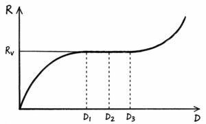
When the curve becomes nearly flat, it indicates that further changes in the position of the voltage probe do not significantly affect the measured resistance. The resistance corresponding to this flat portion of the curve is considered the stable and reliable value of the tower footing resistance.