
The a operator is one of the most important mathematical concepts used in the analysis of three-phase unbalanced systems and asymmetrical faults. It provides a simple way to represent the phase displacement between the three phases and is extensively used in symmetrical component analysis, sequence networks, and power-system fault calculations.
In this article, we will develop the concept step by step, starting from the basic representation of a phasor and finally arriving at the matrix representation of three-phase unbalanced currents.
What is the a Operator?
In a balanced three-phase system, the phase currents are displaced from each other by 120o. The a operator is a complex unit operator used to represent this 120o phase displacement. It is defined as, \[a = 1\angle120^\circ\]In rectangular form,\[a = \cos120^\circ + j\sin120^\circ\]\[\boxed{a=-0.5+j0.866}\] The magnitude of a is one, so it is a unit phasor. Its main purpose is to rotate a phasor by 120o.
Basic Phasor Representation
Before understanding the a operator, let us first understand how a phasor can be represented using complex numbers. Consider a current phasor (I) making an angle (\theta) with the horizontal X-axis. The horizontal component of the phasor is \[I\cos\theta\]The vertical component is\[I\sin\theta\]
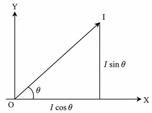
Therefore, the phasor can be represented in rectangular form as\[\boxed{\vec I=I\cos\theta+jI\sin\theta}\]\[\vec I=I(\cos\theta+j\sin\theta)\]According to Euler’s representation,\[
\cos\theta+j\sin\theta=1\angle\theta\]Therefore,\[\boxed{\vec I=I\angle\theta}\]Here, the number one represents the unit phasor. The actual magnitude of the current is multiplied by this unit phasor to obtain the complete current phasor. This simple concept is the basis for understanding the a operator.
Applying the Concept to ‘a’ Three Phase System
Now consider three balanced phase currents.
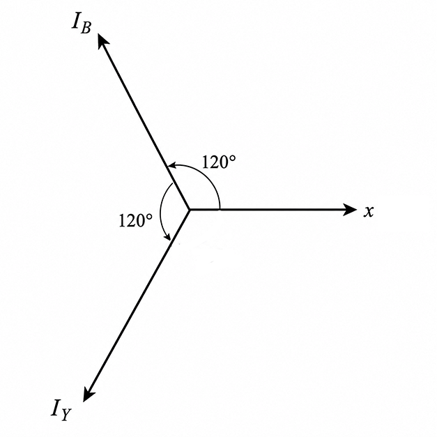
Let the red phase current be our reference phasor\[I_R=I\angle0^\circ
\]The other two phase currents are displaced by 120o. Therefore, depending on the chosen phase sequence, the other phase currents can be represented at 120o and 240o. Let us consider the blue phase current at 120o. We can write,\[I_B=I\angle120^\circ\]Using the rectangular form\[I_B=I(\cos120^\circ+j\sin120^\circ)\]Substituting the values of cosine and sine\[I_B=I\left(-\frac12+j\frac{\sqrt3}{2}\right)\]Therefore,\[I_B=I(-0.5+j0.866)\]But we have already defined\[a=-0.5+j0.866\]Therefore,\[\boxed{I_B=aI}\]This shows the usefulness of the a operator. Instead of repeatedly writing a 120o phase displacement, we can simply multiply the reference phasor by a.
a2 Operator
Now let us consider the yellow phase, which is located at 240o. The yellow phase current can be written as\[I_Y=I\angle240^\circ\]In rectangular form\[I_Y=I(\cos240^\circ+j\sin240^\circ)\]We know that\[\cos240^\circ=-\frac12
\]and\[\sin240^\circ=-\frac{\sqrt3}{2}\]Therefore\[I_Y=I\left(-\frac12-j\frac{\sqrt3}{2}\right)\]or\[I_Y=I(-0.5-j0.866)\]Now let us calculate \(a^2)\.We already know\[a=-\frac12+j\frac{\sqrt3}{2}\]Therefore\[a^2=\left(-\frac12+j\frac{\sqrt3}{2}\right)^2\]Using the square expansion\[(a+b)^2=a^2+2ab+b^2\]we obtain\[a^2=\frac14-j\frac{\sqrt3}{2}+j^2\frac34
\]Since,\[j^2=-1\]we get\[a^2=\frac14-j\frac{\sqrt3}{2}-\frac34\]Therefore,\[\boxed{a^2=-\frac12-j\frac{\sqrt3}{2}}\]or:\[
\boxed{a^2=-0.5-j0.866}\]This is exactly the complex conjugate of a. Since, \[I_Y=I(-0.5-j0.866)\]we can write,\[\boxed{I_Y=a^2I}\]Thus, the three balanced phase currents can be represented using the a operator as,\[\boxed{I_R=I}
\]\[\boxed{I_B=aI}\]\[\boxed{I_Y=a^2I}\]The exact phase labels depend on the phase-sequence convention being used. The important point is that multiplication by \(a\) produces a 120-degree rotation, while multiplication by \(a^2\)produces a \(240^o\) rotation.
a Operator in Symmetrical Components
Now we come to the main application of the a operator. In an unbalanced three-phase system, the three phase currents are not necessarily equal in magnitude or separated by exactly \(120^o\). According to the method of symmetrical components, any set of three unbalanced phase currents can be resolved into three balanced sets:
- Zero-sequence components
- Positive-sequence components
- Negative-sequence components
These three balanced sets are then combined vectorially to reproduce the original unbalanced phase currents. Let the three sequence components be represented by:
- \(I_0\) = zero-sequence current
- \(I_1\) = positive-sequence current
- \(I_2\) = negative-sequence current
All of these quantities are phasors, not scalar quantities.
Red Phase Current
For the reference red phase, the three sequence components are added directly. Therefore\[
\boxed{I_R=I_0+I_1+I_2}\]Here,
- \(I_R\) is the red-phase current.
- \(I_0\) is the zero-sequence current.
- \(I_1\) is the positive-sequence current.
- \(I_2\) is the negative-sequence current.
These are vector quantities, so the equation represents phasor addition.
Yellow Phase Current
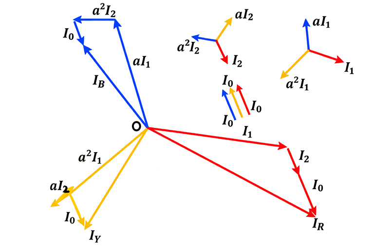
For the yellow phase, the sequence components are rotated according to the a operator relationships. The zero-sequence component has the same phase position in all three phases. The positive-sequence component rotates in the positive phase sequence, while the negative-sequence component rotates in the opposite direction. Therefore\[
\boxed{I_Y=I_0+a^2I_1+aI_2}\]Here, \(a^2I_1\) represents the positive-sequence current of the yellow phase, while, \(
aI_2\) represents the negative-sequence current of the yellow phase.
Blue Phase Current
Similarly, the blue-phase current can be written as\[\boxed{I_B=I_0+aI_1+a^2I_2}\]Therefore, the three phase currents are\[\boxed{I_R=I_0+I_1+I_2}\]\[\boxed{I_Y=I_0+a^2I_1+aI_2}\]\[\boxed{I_B=I_0+aI_1+a^2I_2}\]These equations are fundamental to symmetrical-component analysis.
Matrix Representation
The three equations can be conveniently represented in matrix form.
\[\begin{bmatrix}I_R\\I_Y\\I_B\end{bmatrix}=\begin{bmatrix}1&1&1\\1&a^2&a\\1&a&a^2\end{bmatrix}\begin{bmatrix}I_0\\I_1\\I_2\end{bmatrix}\]This is the matrix transformation from symmetrical components to the actual three-phase currents. The transformation matrix contains the A operator and its square, which makes the representation compact and easy to use in power-system fault calculations.
Why Is the a Operator Important in Fault Analysis?
During an asymmetrical fault, the three phase currents are generally unequal and do not maintain the normal 120-degree relationship. Directly solving the three-phase circuit can therefore become complicated. The method of symmetrical components provides a much simpler approach. The unbalanced current is separated into\[
\text{Zero sequence}+\text{Positive sequence}+\text{Negative sequence}\]Each sequence component can then be analysed using its corresponding sequence network. The A operator provides the mathematical relationship between the sequence components and the actual phase currents. This is why the A operator is extensively used in the analysis of:
- Single line-to-ground faults
- Line-to-line faults
- Double line-to-ground faults
- Unbalanced three-phase systems
- Generator faults
- Transformer fault analysis
- Transmission-line fault analysis
- Power-system protection
- Sequence-network calculations
a, a² and a³ — Easy Way to Remember
A simple way to remember the concept is:
| Operator | Meaning | Phase Rotation |
|---|---|---|
| \(a\) | Unit phasor | 120° |
| \(a^2\) | Square of a operator | 240° |
| \(a^3\) | Cube of A operator | 360° = 0° |
| \(a^3=1\) | Returns to original position | — |