Suppose there is a conductor with a charge of q per unit length. Also, we consider two arbitrary points, P1 and P2, near the conductor. Here, D1 is the distance of P1 from the center of the conductor. D2 is the distance of P2 from the center of the conductor.
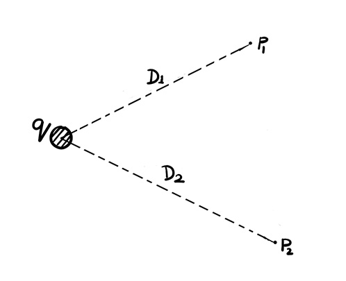
The general expression for the electric field at any arbitrary point at a distance r from the center of the conductor is given as,\[E(r)=\frac{q}{2\pi\varepsilon_0 r}\]Here, \(\varepsilon_0 \) is the absolute permittivity of vacuum (or air). Here, we have placed the conductor in the air, and we have considered P1 and P2 points in the air surrounding the conductor. Therefore, the potential difference between P1 and P2 will be\[V_{P_1P_2}=-\int_{D_2}^{D_1} Edr\]Now, we have already mentioned the expression for E(r), so we can write this as\[V_{P_1P_2}=-\int_{D_2}^{D_1}\frac{q}{2\pi\varepsilon_0 r}dr\]
Therefore, the equation is,\[V_{P_1P_2}=-\frac{q}{2\pi\varepsilon_0 r}\int_{D_2}^{D_1}\frac{dr}{r}\]\[\Rightarrow V_{P_1P_2}=-\frac{q}{2\pi\varepsilon}\left[\ln r\right]_{D_2}^{D_1}\]\[\Rightarrow V_{P_1P_2}=-\frac{q}{2\pi\varepsilon}
\ln\left(\frac{D_1}{D_2}\right)\]\[\Rightarrow \boxed{V_{P_1P_2}=\frac{q}{2\pi\varepsilon}\ln\left(\frac{D_2}{D_1}\right)}\]
Potential Difference Between Two Conductors of a Group of Three Conductors
Section 1: Suppose there are three conductors, A, B, and C. We place these conductors at three positions, marked as 1, 2, and 3. Conductor A contains qA charge per unit length, while conductors B and C contain qB and qC charge per unit length, respectively. The distance between positions 1 and 2, or equivalently between positions 2 and 1, is denoted by D12 and D21, respectively. Similarly, the distance between positions 2 and 3, or equivalently between positions 3 and 2, is denoted by D23 and D32, respectively. The distance between positions 3 and 1, or equivalently between positions 1 and 3, is denoted by D31 and D13, respectively.
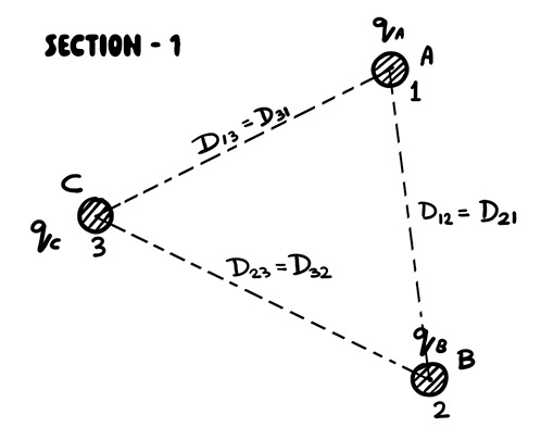
Here, we shall see the potential difference appearing between conductors A and B due to the charges on all three conductors.
Voltage between Position 1 and 2 due to Charge in Conductor C
For that, we will first consider conductor C carrying a charge of qC. For the time being, we will ignore conductors A and B and derive the potential difference between positions 1 and 2 due only to the charge on conductor C.
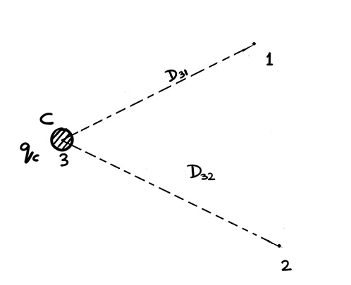
The voltage between positions 1 and 2 due to the charge on conductor C can be written as, \[V_{12(C)}=\frac{q_C}{2\pi\varepsilon_0}\ln\left(\frac{D_{32}}{D_{31}}\right) \]
Voltage between Position 1 and 2 due to Charge in Conductor A
Now, we shall calculate the potential difference between positions 1 and 2 due to the charge on conductor A only. So, we have omitted conductors B and C for the time being and considered only conductor A carrying a charge of qA coulomb per unit length. Now, let rA be the radius of conductor A.
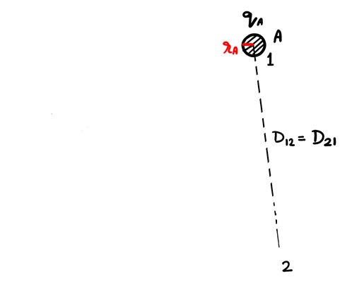
As the charge is distributed over the surface, we shall consider the distance from the surface of the conductor A to position 2.
Hence, the final expression will be, \[V_{12(A)}=\frac{q_A}{2\pi\varepsilon_0}\ln\left(\frac{D_{12}}{r_A}\right)\]
Voltage between Position 1 and 2 due to Charge in Conductor B
Now, we shall calculate the potential difference between positions 1 and 2 due to the charge on conductor B only. So, we have omitted conductors A and C for the time being and considered only conductor B carrying a charge of qB coulomb per unit length. Now, let rB be the radius of conductor B.
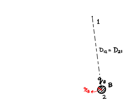
For similar reasons, we shall consider the distance from the surface of the conductor B to position 1. Therefore, the expression of the potential difference between 1 and 2 is\[V_{12(B)}=-\frac{q_B}{2\pi\varepsilon_0}\int_{r_B}^{D_{21}}\frac{dr}{r}\]\[\Rightarrow V_{12(B)}= \frac{q_B}{2\pi\varepsilon_0} \ln\left(\frac{r_B}{D_{21}}\right)\]
Voltage due to Charge in all Three Conductors
Therefore, the potential difference or voltage between positions 1 and 2 due to the charge in all three conductors will be\[V_{12}=\frac{q_A}{2\pi\varepsilon_0}\ln\left(\frac{D_{12}}{r_A}\right)+\frac{q_B}{2\pi\varepsilon_0}\ln\left(\frac{r_B}{D_{21}}\right)+\frac{q_C}{2\pi\varepsilon_0}\ln\left(\frac{D_{32}}{D_{31}}\right)\]\[\boxed{V_{12}=\frac{1}{2\pi\varepsilon_0}\left[q_A\ln\left(\frac{D_{12}}{r_A}\right)+q_B\ln\left(\frac{r_B}{D_{21}}\right)+q_C\ln\left(\frac{D_{32}}{D_{31}}\right)\right]}\]
Section 2: Actually, this transmission line is transposed. So, we place conductor A from position 1 to position 2, conductor B from position 2 to position 3, and conductor C from position 3 to position 1.

Now, we shall calculate the potential difference between conductors A and B. That means we shall calculate the potential difference between positions 2 and 3 due to the charges on all the conductors. In that case, we can write the voltage between positions 2 and 3 as, \[\boxed{V_{23}=\frac{1}{2\pi\varepsilon_0}\left[q_A\ln\left(\frac{D_{23}}{r_A}\right)+q_B\ln\left(\frac{r_B}{D_{32}}\right)
+q_C\ln\left(\frac{D_{13}}{D_{12}}\right)\right]}\]
Section 3: In this section, we place conductor A from position 2 to position 3, conductor B from position 3 to position 1, and conductor C from position 1 to position 2.
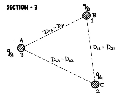
Now, we shall derive the potential difference between conductors A and B. That means we shall calculate the potential difference between positions 3 and 1 due to the charges on all the conductors. In that case, we can write the voltage between positions 3 and 1 as, \[\boxed{V_{31}=\frac{1}{2\pi\varepsilon_0}\left[q_A\ln\left(\frac{D_{31}}{r_A}\right)+q_B\ln\left(\frac{r_B}{D_{13}}\right)+q_C\ln\left(\frac{D_{21}}{D_{23}}\right)\right]}\]
Average Voltage of Conductor A and B
Now, the average voltage between conductors A and B, considering all three sections of transposition, is given by,