
Type Tests on Suspension Clamp for HTLS Conductor
The tests are listed according to the Guidelines for Rationalized Use of High Performance Conductors
Central Electricity Authority (CEA)
Magnetic Power Loss Test
This type test measures the magnetic losses of suspension clamps. The test shall be carried out as agreed between purchaser and supplier.
Here, we pass a power frequency current through a suitable length of conductor. Then we measure the power loss. Now, we fit a certain number of suspension clamps on the conductor. Again, we measure the wattage with the fittings assembled on the conductor. In case of AG suspension clamps, we assemble the armour rods.
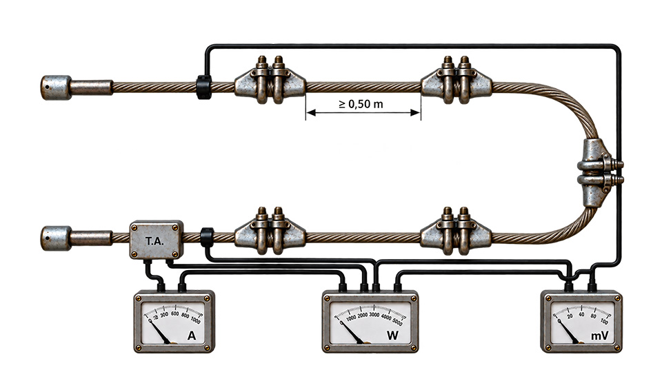
We keep the test circuit geometry exactly the same for both measurements. In each case, we allow the conductor to reach its steady temperature.
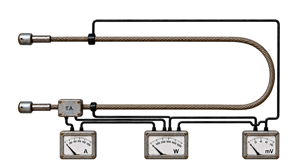
To measure the power losses of the fittings, the standards recommends to use a minimum five suspension clamps. We mount the clamps on the conductor with a minimum spacing between them not less than 50 cm. The fittings under test shall be complete with all components assembled as defined in the supplier’s drawing of the fitting.
We apply an AC voltage at a frequency of 50 Hz. We keep the magnitude of the current according to table given bellow.
| Conductive cross-section (mm²) | Aluminium and aluminium alloy (A) |
|---|---|
| 25 | 115 |
| 50 | 175 |
| 75 | 230 |
| 100 | 275 |
| 150 | 355 |
| 200 | 435 |
| 250 | 500 |
| 300 | 565 |
| 400 | 680 |
| 500 | 785 |
| 600 | 875 |
| 700 | 955 |
| 800 | 1 025 |
| 900 | 1 100 |
| 1 000 | 1 170 |
Acceptance criteria
We accept the test if the magnetic losses of the clamps are less than or equal to the power losses per unit length of the conductor. The condition corresponds to the relation:\[ \frac{P_D-P_C}{N}\leq \frac{P_C}{L} \]Where, \(P_C\) = the power losses of the reference length of the conductor without fittings, in watts;
\(P_D\) = the power losses of the reference length of the conductor with fittings, in watts;
\(L\) = the reference length of the conductor in metres;
\(N\) = the number of fittings mounted.
Clamp Slip Strength
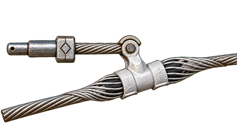
As per IS 2486 (Part 2), the slip strength test is conducted on an Armour Grip (AG) type suspension clamp by applying a horizontal tensile load to the conductor after the conductor has been properly fitted in the AG suspension clamp.
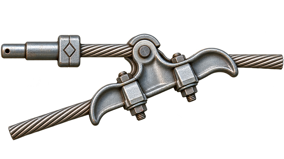
During the test, the applied horizontal load shall be not less than 12.5% of the Ultimate Tensile Strength (UTS) of the conductor. The UTS of the conductor can be obtained from the approved GTP (Guaranteed Technical Particulars) or from the relevant conductor specification. The maximum horizontal load applied to the conductor during the slip strength test shall be less than 20% of the UTS of the conductor.
The CEA guideline provides an example for a 400 kV transmission system. In this example, the horizontal tensile load applied during the slip strength test is specified within the range of 20 kN to 29 kN. In other words, for the particular conductor and clamp arrangement covered by that example, the applied horizontal tensile load should be not less than 20 kN and not more than 29 kN, subject to the applicable test requirements.
Ozone Test on Elastomer
Vertical Damage Load and Failure Load Test — IEC: 61284
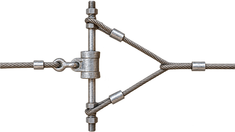
We carry out the test according to the same or equivalent arrangement shown on the image below.
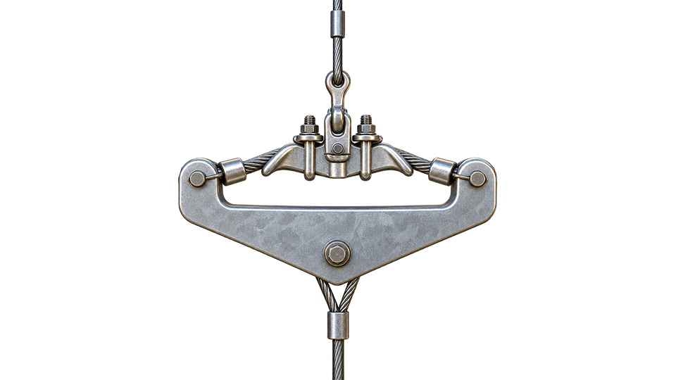
We mount the clamp in a tension testing machine. Here we have shown only the arrangement of the clamp portion.
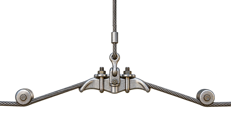
For Armour Grip Suspension Clamp or AG Suspension Clamp we shall apply armour rods to the conductor. Since, armour rods are used in actual service of the clamp.
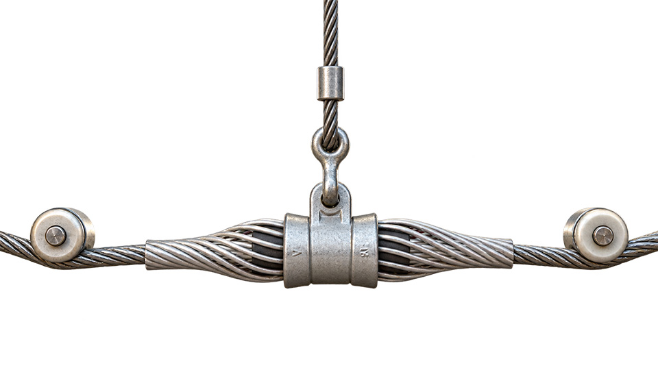
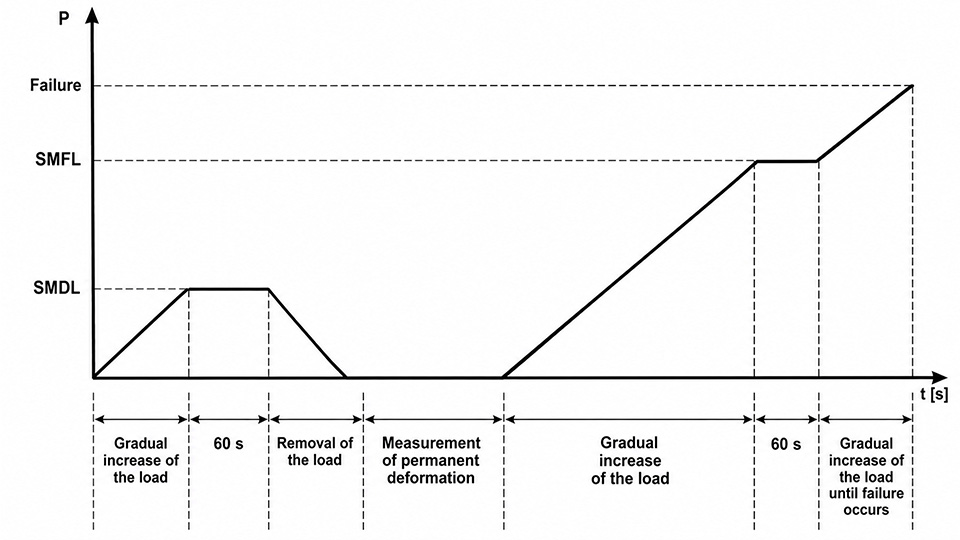
First step : Then we increase the load gradually to the specified minimum damage load (SMDL). Then we keep it constant for 1 minute or 60 s. After that, we unload the clamp. Lastly we perform measurements of the permanent deformations. Actually we marked points at different locations on the tensed part of the clamp. Then we measure the point to point distance to ensure degree of deformation during the test.
Second step : Now instead of the conductor, we insert a rigid bar of suitable size in the clamp. The we install it on in the tension testing machine.
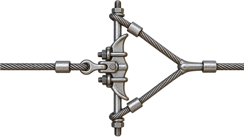
Now, we load the clamp gradually increase the load to the specified minimum failure load (SMFL).
Then we keep the load constant for 60 seconds again. Thereafter, we gradually increase the load until failure of the fitting.
NOTE — For very high mechanical failure loads, we can stop the test at 1.2 times the specified minimum failure load. This is in the view of the safety of equipment and operators.
Type Tests on Dead end Tension Assembly
Electrical Resistance Test for Dead End Assembly — As per IS:2486-(Part-I)
b) Heating cycle test for dead end Assembly — As per Appendix-I
c) Slip strength test for dead end assembly — As per Appendix-I
d) Ageing test on filler (if applicable) — As per Appendix-I