In this article, we discuss the voltage ratio test for a three-phase power transformer. The voltage ratio test of a three-phase transformer is quite simple. We use a TTR meter, which means Transformer Turns Ratio Meter or Transformer Turns Ratio Measuring Instrument.
This instrument commonly has six probes: three for the high-voltage terminals and three for the low-voltage terminals. The high-voltage probes are marked as H1, H2, and H3. Besides, the low-voltage probes are marked as X1, X2, and X3.
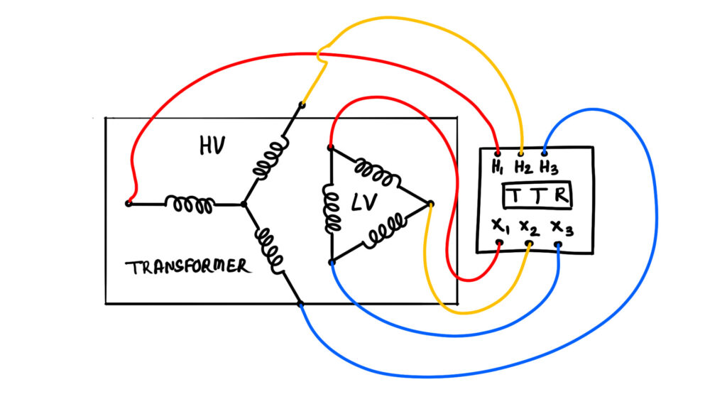
Connection for Turns Ratio Test
Obviously, before the test, we have to disconnect the transformer from the system. Also, we have to check all the earthing connections of the transformer. These earthing terminals should be properly connected to the earth. Then, we connect the high-voltage probes H1, H2, and H3 to the red, yellow, and blue phase HV studs of the transformer. Then we have to connect the X1, X2, and X3 probes of the TTR meter to the red, yellow, and blue phase LV studs of the transformer.
Turns Ratio Test Procedure
First, we make the tap changer switch at position 1. Then we have to switch on the TTR meter. After that, we have to select the proper vector group of the transformer on the TTR meter. The rating plate of the transformer shows it as either Dyn11, or Ynd1, etc. Whatever it may be, we have to select it on the TTR meter.
Then the TTR meter injects a voltage into the high-voltage winding. The injected voltage will be about 40 V to 100 V AC at the power frequency of 50 Hz, irrespective of the voltage level of the transformer. Because this low voltage is enough to excite the transformer winding and induce voltage in both windings.
Then the TTR meter measures the injected voltage across the HV winding and the corresponding induced voltage across the LV winding. By calculating the ratio of the HV voltage and the LV induced voltage, it can easily determine the turns ratio. Also, it gives the measurement of phase displacement between the voltages induced across the high-voltage winding and the low-voltage winding. The measured ratio must be within ±0.5% of the rated voltage ratio at that tap position, that is, at tap position 1.
After taking the record, we will change the tap position from 1 to 2 and again repeat the measurement with the same injected voltage. We will continue this procedure until the last tap position, that is, up to the 17th step. Every time, we will compare the measured ratio with the rated voltage ratio corresponding to that tap position, and it must be within ±0.5% as per the standard.
In this way, we perform the TTR (Transformer Turns Ratio) measurement.