
In this article, we shall discuss the earth fault protection of a balanced three-phase network.
Balanced Three-Phase Network
Suppose this is a balanced three-phase network. Also, assume this is the representation of a three-phase star-connected winding of a power transformer. Although we can represent all balanced three-phase networks in the same manner, in our case we are showing the winding network of a transformer.
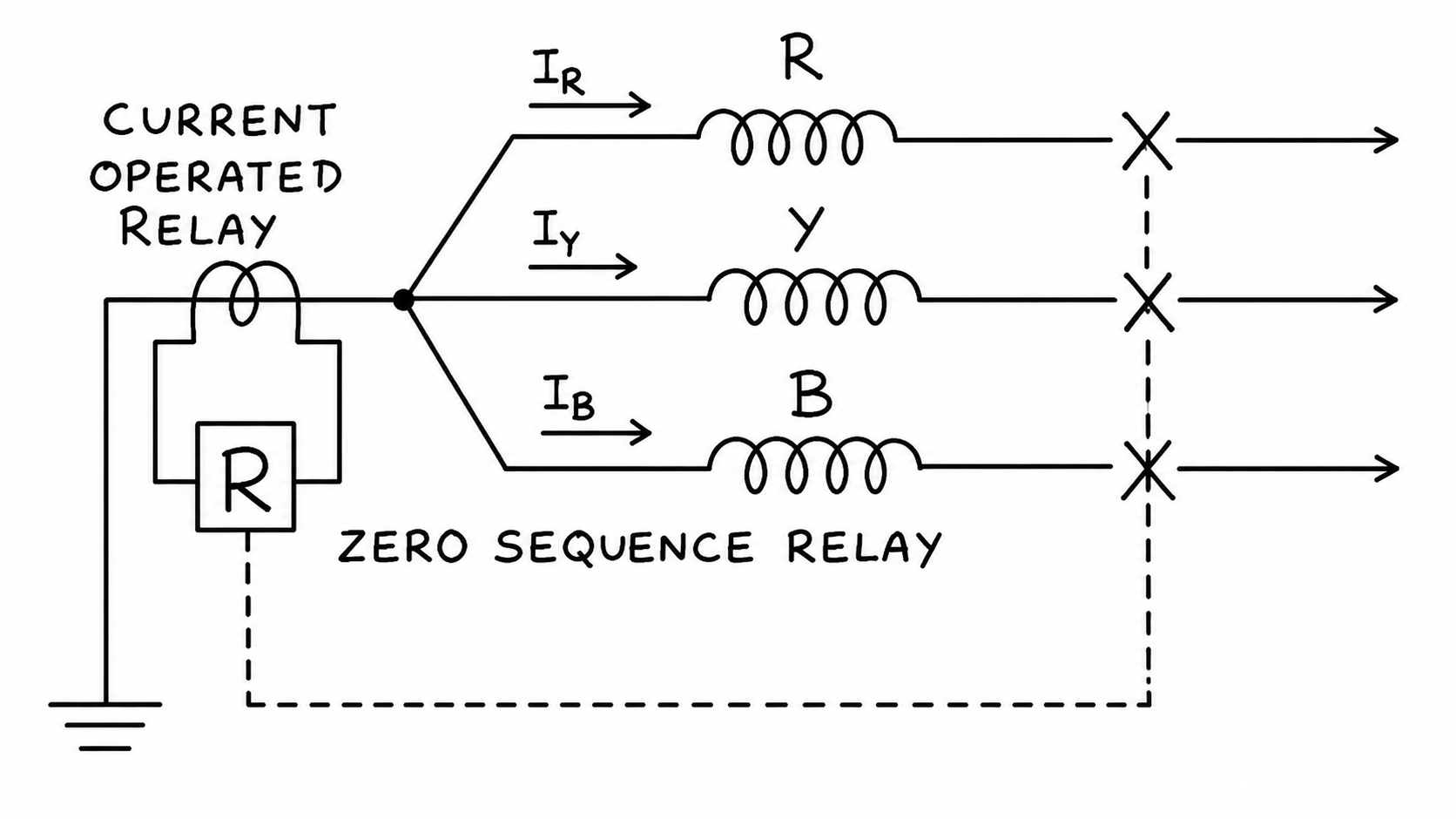
Obviously, under balanced conditions, the sum of all three-phase currents is zero. That means,
IR + IY + IB = 0
This balanced condition remains intact under all loading conditions.
That means no current flows through the path connecting the star point to the earth. In other words, no current flows through the neutral connection of the transformer.
Phase-to-Phase Short-Circuit Fault
Now, suppose a phase-to-phase short-circuit fault occurs between the R and Y phase terminals of the transformer. In that case, there shall be a closed loop between the R and Y phases. So, the short-circuit current circulates in the loop created by the star point, the R-phase winding, the Y-phase winding, and the short-circuit path. As the fault current circulates in this loop, there will also be no current flowing through the neutral path of the transformer.
Three-Phase Short-Circuit Fault
Let us now examine the situation of a three-phase fault. In that case, the short-circuit path connects all three phases together. The fault current circulates inside the loops created by the star point, the phase windings, and the short-circuit path. In that situation also, no current shall be diverted through the neutral path.
Single Phase-to-Earth Fault
Now, consider a situation where any one of the phase connections touches the earth or ground. In that case, a short-circuit path is created between that phase and the earth through the neutral connection. Obviously, the fault current starts circulating through this path. Also, due to the short circuit to earth, the currents of all three phases are no longer balanced. Hence, the sum of all three-phase currents is no longer zero.
IR + IY + IB = 3IO ≠ 0
Obviously, this unbalanced current flows through the neutral path of the system.
Double Phase-to-Earth Fault
In the case of a double-phase-to-earth (or ground) fault, the same thing happens. Since the fault gets a path through the earth, a portion of the fault current also circulates through the neutral. This is because there is an earth loop in addition to the phase-to-phase loop.
So, for single-phase-to-ground (L–G) and double-phase-to-ground (L–L–G) faults, there will always be a zero-sequence current flowing through the neutral connection.
Earth Fault Relay
Now, we place a current-operated relay in the neutral connection. The current-operated relay is a type of overcurrent relay. However, the current pickup setting for this relay is much lower than the actual overcurrent setting. This is because any unbalanced current always flows through the neutral connection. This unbalanced current may be much smaller than the actual fault current because the fault may have other paths to flow to the earth. Also, there may be highly resistive or highly reactive paths. This is why the earth fault current may be much lower than that expected in a directly and effectively earthed system.
Relay Operation During Earth Fault
So, during single-line-to-earth (L–G) and double-line-to-earth (L–L–G) faults, the relay operates to trip the circuit breaker for earth fault protection.