
An air blast circuit breaker is a circuit breaker that interrupts normal load current or fault current by means of a high-pressure blast of air inside the interrupting chamber.
Why do we call it an Air Blast Circuit Breaker?
A circuit breaker performs two main functions: first, the opening and closing of its contacts, and second, the quenching of the electric arc formed during the opening operation. Here, highly compressed air, performs both these functions. That is why it is called an air blast circuit breaker.
Basic Construction of an Air Blast Circuit Breaker
The main component of an air blast circuit breaker is a large air reservoir. In this reservoir air is stored at a very high pressure, typically around 20 to 30 bar, with the help of an air compressor. An air pipeline is provided between this compressed-air reservoir and the interrupting chamber of the circuit breaker. An air valve is installed in this pipeline. This valve is connected to the operating mechanism of the circuit breaker. Whenever a trip signal is received, the valve opens and allows compressed air to flow into the interrupting chamber.
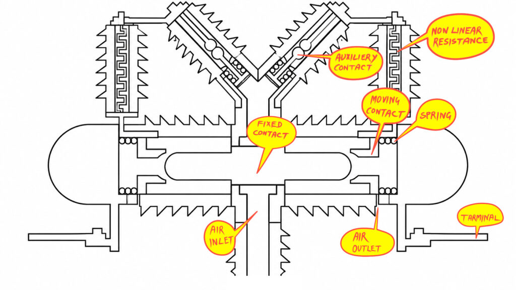
Interrupting Chamber
A fixed contact is fitted at the center of the chamber. Two moving contacts are placed on opposite sides of this fixed contact. These moving contacts are kept in contact with the fixed contact assembly by means of spring pressure.
Whenever a trip signal is received by the operating mechanism, the air valve operates and allows compressed air to flow from the reservoir into the interrupting chamber. The high-pressure air pushes the moving contacts against the spring pressure. As a result, the moving contacts travel backward and get separated from the fixed contact. Consequently, the contacts opens.
Arc Quenching
During this opening operation, an electric arc is formed between the fixed and moving contacts. As the moving contacts separate from the fixed contact assembly, a gap is created between them. This gap provides a path for the compressed air to flow towards the exhaust outlet of the interrupting chamber. As a result, the high-speed air flowing through this gap blows the arc away from the contact region. So it rapidly cools and deionizes the arc path, and helps extinguish the arc. As a result, the arc is quenched, and the current is finally interrupted.
Air Exhaust
Now, the exhaust outlet of the interrupting chamber is mechanically designed in such a way that the opening and closing of the exhaust passage depend on the travelling distance of the moving contacts. In other words, due to the high pressure of the air blast, the moving contacts slide backward. After travelling a certain predetermined distance, the moving-contact mechanism blocks the exhaust opening of the interrupting chamber.
Hence, after the arc is quenched, the pressurized air gets trapped inside the interrupting chamber. The valve through which compressed air enters the chamber is also designed to prevent the reverse flow of air.
Therefore, due to the trapped pressurized air, the moving contact cannot return to its original closed position. This is because the force exerted by the internal air pressure is greater than the opposing spring force. As a result, the moving contact remains in its open position.
Video on Air Blast Circuit Breaker
Resistance Switching in an Air Blast Circuit Breaker
Now, a non-linear resistance is connected between each pair of fixed and moving contacts through an auxiliary contact arrangement. The circuit breaker is designed in such a way that, during the opening operation, the high-pressure air also pushes the moving contact backward. At the same time, this compressed air also pushes a piston attached to the moving auxiliary contact.
As a result, the moving auxiliary contact touches the fixed auxiliary contact and completes the circuit of the non-linear resistance. In other words, during the opening operation, a non-linear resistance is connected across the fixed and moving contacts.
Therefore, the arc that continues to exist in the contact gap gets an alternative parallel resistive path. The presence of this resistance helps limit the transient overvoltage that may appear across the circuit breaker contacts during current interruption. After the arc is quenched, the auxiliary contact arrangement operates under spring action and disconnects the resistance from the parallel path.
This process is known as resistance switching, which is an important feature used in certain air blast circuit breakers to control switching overvoltages and improve interruption performance.
Series Connection of Interrupting Units for Very High-Voltage Applications
Now, a single interrupting unit of an air blast circuit breaker cannot necessarily withstand the entire voltage of a very high-voltage system. Therefore, for very high-voltage switching applications, multiple interrupting units are connected in series, one after another, so that the complete circuit breaker can withstand the required system voltage.
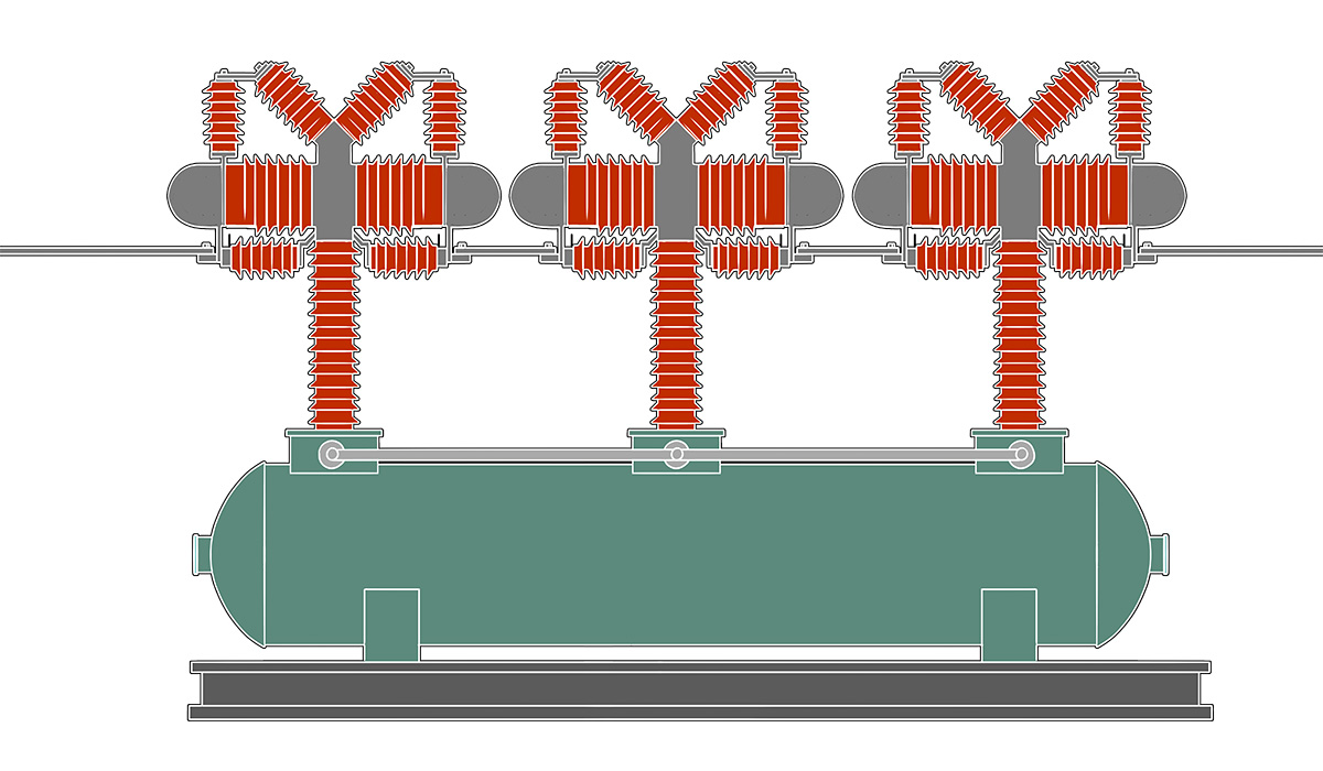
For example, a very high-voltage air blast circuit breaker may have three interrupting chambers connected in series per phase. Each interrupting chamber may contain two contact gaps, forming a double-break arrangement. Therefore, the total number of interrupting gaps becomes, 3×2 = 6.
In other words, the complete circuit breaker has six interrupting gaps connected in series per phase.
Grading Capacitor of ABCB
Since these six interrupting gaps are connected in series, theoretically, each gap should withstand one-sixth of the total voltage appearing across the circuit breaker, assuming equal voltage distribution.\[V_{gap}=\frac{V_{\text{total}}}{6}\]
However, in practice, the voltage may not be distributed equally across all six interrupting gaps. Therefore, to ensure a more uniform voltage distribution, grading capacitors are provided in certain air blast circuit breakers. A grading capacitor is connected across each interrupting unit, or across the relevant contact gap, depending on the design.
The main function of these grading capacitors is to distribute the voltage more uniformly across the series-connected interrupting gaps. This helps prevent excessive voltage stress across any individual contact gap and improves the overall dielectric performance of the circuit breaker.