Nowadays, utilities connect many power system components in parallel. These components include generating stations, step-up transformers, transmission lines, step-down transformers etc. This arrangement reduces the total reactance of the power system. As a result, the short-circuit level increases. The short-circuit level includes short-circuit current and short-circuit MVA. These values can increase at different points in the power system.
Impact on Power-System Equipment
Because of the higher short-circuit current, existing circuit breakers may become inadequate. They may not be able to safely make or break the increased fault current. Therefore, utilities may need to increase the making and breaking capacities of the circuit breakers. They may also need to upgrade other equipment. This equipment may include, current transformers, isolators, jumpers, droppers and connecting conductors etc.
Need for Current-Limiting Reactors
However, replacing all these components is not practical. The short-circuit level may increase again in the future. Utilities can solve this problem by using series reactors. These reactors are also called current-limiting reactors. They are installed at selected locations in the power system. A series reactor limits the short-circuit current. Therefore, utilities may not need to replace all existing equipment. The system can continue to operate safely. The equipment can remain within its short-circuit ratings.
How a Series Reactor Works
Now, let us see how a reactor limits the short-circuit current. Every power system already has some reactance. This reactance comes from different components. These components include generators, step-up transformers, transmission lines, step-down transformers, and other system components. The short-circuit current at a point can be approximately calculated as,
\[\text{Short Circuit Current}=\frac{\text{System Voltage}}{\text{Total Equivalent Reactance}}\]
Now, if we insert an additional reactance into the system by using a series reactor, the total reactance between the source and the fault location increases. Therefore,
\[\text{Short Circuit Current}=\frac{\text{System Voltage}}{\text{Increased Reactance}}\]
Fault-Current Limitation
When the total reactance increases, the short-circuit current decreases. The reactor therefore limits the fault current. The circuit breakers and other equipment can then safely handle the fault current. This is the basic function of a series reactor. It is also called a current-limiting reactor.
Strategic Locations of Reactors
It is almost impossible to insert a series reactor at every part of a power system. Therefore, we have to choose some strategic locations to insert series reactors in the system.
Depending on their locations, series reactors can mainly be classified as:
- Generator reactors
- Feeder reactors
- Bus-bar reactors
These are the three main locations where series reactors are generally provided.
Generator Reactor
When we insert a series reactor between a generator and the generating station bus, we call it a generator reactor or generator current-limiting reactor. If a short circuit occurs in the system, a large fault current flows through the reactor. The generator reactor limits this fault current.
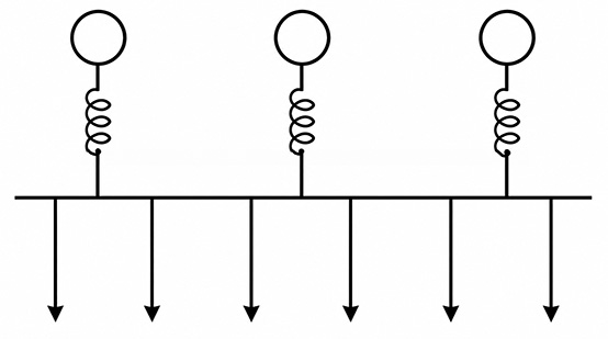
However, due to the large fault current, a significant voltage drop occurs across the reactor. As a result, the voltage at the generating station bus may drop considerably during the fault. This is the main disadvantage of this arrangement. Therefore, the use of series reactors between generators and the generating station bus has become less common nowadays.
Feeder Reactor
Sometimes, we use a series reactor, or current-limiting reactor, in each outgoing feeder of a substation. This arrangement is called a feeder reactor. If a fault occurs in a particular feeder, the reactor limits the fault current flowing through that feeder. During the fault, the voltage of the faulty feeder may drop significantly due to the voltage drop across the reactor. However, the rest of the system can continue to operate at nearly normal voltage.
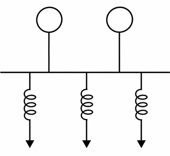
The main disadvantage of this arrangement is that a separate reactor has to be provided for each feeder. Therefore, providing series reactors for every outgoing feeder can become expensive.
Bus-Bar Reactor
Sometimes, utilities use a bus-bar reactor. In this arrangement, the bus is divided into different sections, and a series reactor is placed between these bus sections. If a fault occurs on one section of the bus, the reactor limits the fault-current contribution coming from the other section of the bus.
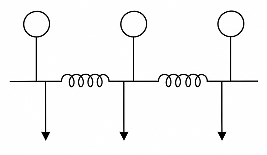
Therefore, the reactor reduces the effect of the short-circuit fault on the healthy section of the bus. The voltage of the healthy section may remain relatively undisturbed because of the presence of the series reactor between the two bus sections.
Classification of Current-Limiting Reactors
So, depending on their locations in the power system, current-limiting reactors can mainly be classified as generator reactors, feeder reactors, and bus-bar reactors.
Types of Current Limiting Reactor or Series Reactor
The high faults current should not saturate the core of a reactor. Fault current is much higher than normal current. So, to keep the core of reactor unsaturated, a reactor needs a very large cross-section of its core. Air core may solve this issue of saturation. The utilities use mainly Dry-type Air Core Reactors and Oil Immersed Air Core Reactor.
Dry Type Reactors
Dry type reactors generally use natural or forced air cooling. The utilities use dry type reactor only up to 33 kV systems. They prefer, oil immersed designs of reactor for higher voltage system. Oil makes the size of the reactor more compact compared to a dry type reactor. A dry type reactor needs a large clearance from adjacent constructional work and iron works. Because of the absence of low reluctance or iron paths, the reactance of air-cored reactors becomes almost constant.
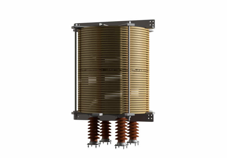
Air Core Oil Immersed Reactor
In an oil-immersed reactor uses an iron made oil tank. The reactor windings are placed inside this oil filled iron tank. When the current increases significantly, the magnetic flux increases. This flux may then link with the iron body of the tank. Hence, the flux induces eddy currents in it. These eddy currents can cause unnecessary heating and may create hot spots in the tank body.
To avoid this problem, the manufacturer provides laminated iron shields around the windings. These laminated iron shield provides a path for the magnetic flux. Therefore, it prevents a the flux to enter in the surrounding iron tank.
However, when the fault current increases abruptly, the iron shields may approach magnetic saturation. As a result, the overall reactance of the reactor may decrease up to 10% during the fault condition.
Iron Core Oil Immersed Reactor
Here, the winding contains an iron core inside it. However, the core contains air gaps. Because, the air gaps increase the magnetic reluctance of the core. Therefore, these air gaps prevent saturation due to high fault current.