In this article, we will discuss the Winding Temperature Indicator of a power transformer. First, let us understand what a Winding Temperature Indicator actually is.
Inside the marshalling box of a power transformer in a substation, we generally see two temperature indicators, and sometimes even three temperature indicators. Among these, one is the HV Winding Temperature Indicator, one is the LV Winding Temperature Indicator, and another one is the Oil Temperature Indicator.
In this article, we will mainly discuss the HV Winding Temperature Indicator and the LV Winding Temperature Indicator. Although the working principle of the HV and LV Winding Temperature Indicators is the same, both arrangements are practically identical. The main difference is that the HV Winding Temperature Indicator is connected with the HV-side CT, whereas the LV Winding Temperature Indicator is connected with the LV-side CT.
Importance of Winding Temperature Monitoring
The loading capacity of a transformer, such as 50 MVA, 31.5 MVA, etc., mainly depends upon the permissible temperature rise limit of the transformer. Therefore, for the safe operation of a transformer, it is always necessary to continuously monitor the temperature rising pattern of the transformer. The Winding Temperature Indicator performs this important function.
Generally, a Winding Temperature Indicator contains four Normally Open (NO) contacts. These NO contacts can be set at different temperature levels. As the temperature rises, the first NO contact closes after reaching a certain temperature. If the temperature rises further, the second NO contact closes. After another pre-specified temperature limit, the third NO contact closes. Finally, if the temperature increases further, the fourth NO contact closes.
Functions of Different NO Contacts
Each of these NO contacts performs a specific function.
- When the first NO contact closes, the transformer cooling fan circuit starts operating. In other words, the forced air cooling system of the transformer becomes operational.
- When the second NO contact closes, the oil circulation pump starts operating for forced oil circulation inside the transformer.
- If the temperature further increases due to excessive loading, the third NO contact closes and the High Winding Temperature Alarm starts operating.
- If the transformer is still not attended, and no attempt is made to reduce the load, then finally the fourth NO contact closes and actuates the transformer trip circuit. As a result, the transformer gets isolated from the system through intertripping from both the HV and LV sides.
Why Direct Measurement of Winding Temperature is Not Possible
Actually, it is not possible to directly measure the temperature of the conductor portion of the transformer winding because the entire winding conductor, whether copper or aluminum, remains covered by thick paper insulation. Therefore, no temperature sensor can be directly inserted inside the winding conductor.
For this reason, an indirect method is used for winding temperature measurement, and this indirect method is implemented through the Winding Temperature Indicator.
Construction and Working Principle of WTI
The main sensing element inside the Winding Temperature Indicator is the Bourdon Tube. The Bourdon Tube is a semicircular metallic tube connected through a capillary tube with a mercury bulb.
This mercury bulb is inserted inside the oil pocket provided on the top cover of the transformer tank.
The oil pocket is basically a welded well-type pocket provided on the transformer top cover. This pocket does not have any direct connection with the transformer oil circulation path. However, separate transformer oil remains inside this pocket. A copper made mercury bulb is inserted into this oil-filled pocket.
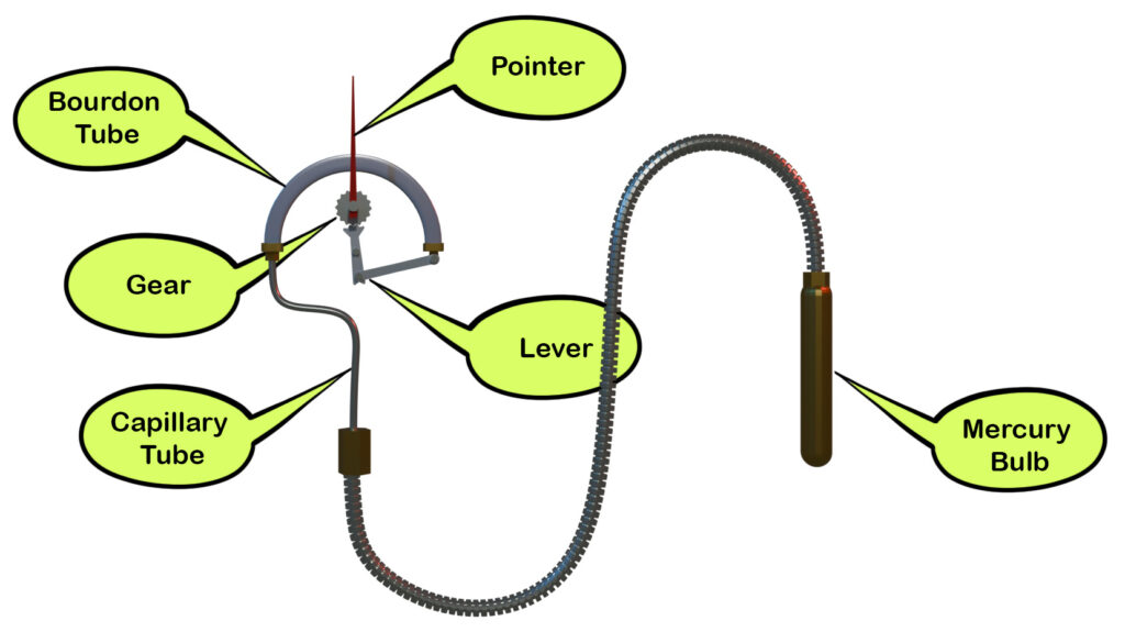
The capillary tube connected with the bulb ultimately joins one end of the Bourdon Tube. The Bordon tube is fitted inside the Winding Temperature Indicator.
The Bourdon Tube is mechanically connected with a lever and gear arrangement. The temperature indicating pointer is attached with the shaft of the gear. Due to the deformation of the curvature of the Bourdon Tube, the lever slides and rotates the gear mechanism. Since the pointer is attached with the gear shaft, the pointer also rotates over the temperature dial of the Winding Temperature Indicator.
In this way, the oil temperature can be measured through the angular movement of the pointer. When the oil temperature increases, the liquid inside the bulb expands, causing the Bourdon Tube to deform further and rotate the pointer toward a higher temperature indication. Similarly, when the temperature decreases, the pointer moves toward a lower temperature indication.
Indirect Measurement of Winding Temperature
Actually, the temperature of the copper or aluminum winding conductor is directly proportional to:
- The current flowing through the conductor, and
- The surrounding hot oil temperature inside the transformer.
Since the winding conductor temperature cannot be measured directly, an indirect method is used. The winding connection ultimately comes outside through the transformer bushing. Inside the bushing turret portion, surrounding the main conductor rod, a Current Transformer (CT) is installed. This CT is known as the Winding Temperature Indicator CT or WTI CT.
The secondary winding of this CT is connected with a heater coil fitted inside the Winding Temperature Indicator. When the transformer load current increases, the proportional secondary current of the CT also increases. As a result, the heating effect produced by the heater coil also increases. Due to this heating effect, the liquid inside the Bourdon Tube expands further and increases its pressure. Consequently, the Bourdon Tube attempts to straighten further, producing additional movement of the pointer.
Therefore, the pressure developed inside the Bourdon Tube depends upon two effects:
- The oil temperature sensed through the mercury bulb.
- The heating effect produced by the heater coil energized from the WTI CT secondary current.
Based on this combined effect, the Winding Temperature Indicator dial is calibrated to approximately indicate the actual winding temperature.
Mercury Switch Arrangement in WTI
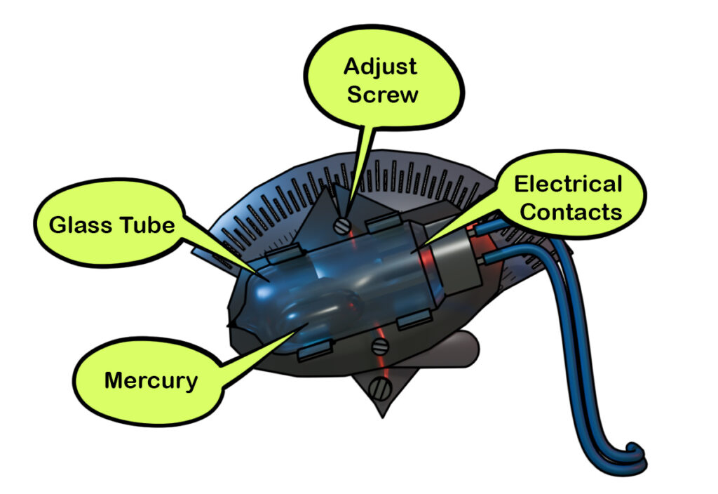
The switching arrangement inside the Winding Temperature Indicator generally uses Mercury Switches. A Mercury Switch is a small glass tube containing a small quantity of mercury along with two electrical contacts.
When the glass tube remains horizontal or slightly tilted, the mercury stays at one end of the tube while the contacts remain open. However, when the tube is tilted beyond a certain angle, the mercury rolls toward the contacts and electrically bridges them, thereby closing the switch. Thus, the operation of a Mercury Switch completely depends upon its angle of alignment.
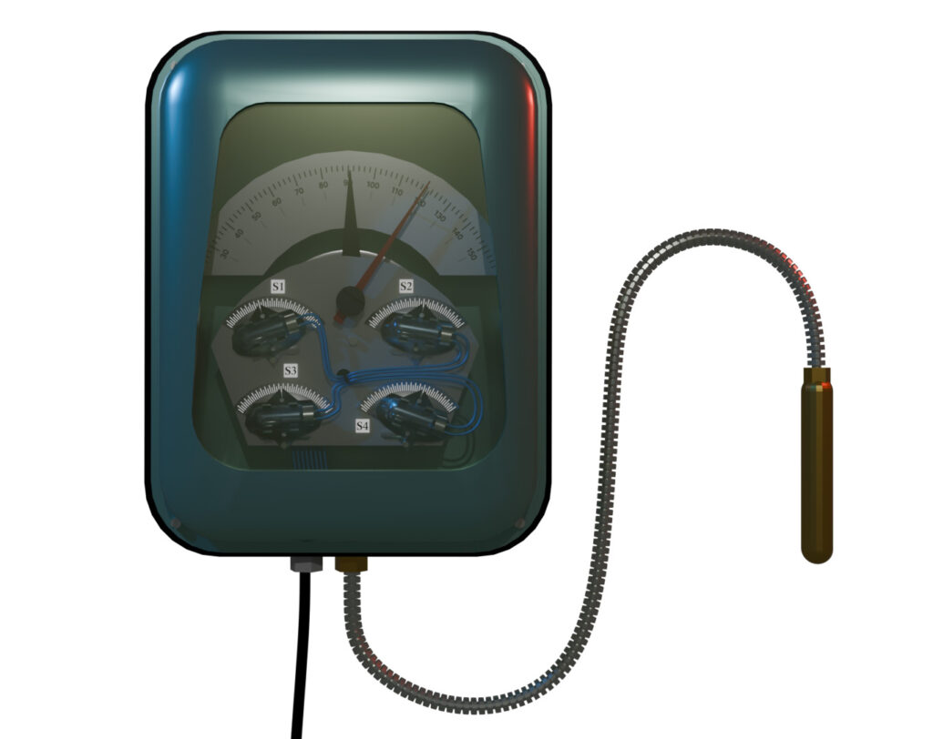
Inside the Winding Temperature Indicator, four Mercury Switches are fitted on a semicircular disk at different angular alignments. These switches are generally identified as S1, S2, S3, and S4.
The pointer is rigidly attached with the semicircular disk. The entire assembly is rigidly fitted with the shaft of the central gear of the Bourdon Tube lever-gear mechanism.
When the transformer temperature increases, the curvature of the Bourdon Tube changes. Due to this, the lever mechanism moves and rotates the gear assembly. Since the pointer and semicircular disk assembly is attached with the same shaft, it rotates simultaneously.
As the disk rotates gradually with increasing temperature:
- First, S1 becomes unbalanced and tilts, thereby closing its contact.
- With further rotation, S2 closes.
- After additional temperature rise, S3 closes.
- Finally, at excessive temperature, S4 closes.
Functions of S1, S2, S3, and S4
The functions of the four Mercury Switches are as follows:
- S1: Starts the transformer cooling fan.
- S2: Starts the transformer oil circulation pump.
- S3: Operates the High Winding Temperature Alarm.
- S4: Operates the transformer trip circuit and isolates the transformer from the system.
Older Type Winding Temperature Indicator Arrangement
Previously, another type of Winding Temperature Indicator arrangement was also used.
In this arrangement, the heater coil was not fitted inside the Winding Temperature Indicator itself. Instead, it was installed around the transformer oil pocket in such a way that the heating effect produced by the secondary current of the WTI CT directly heated the sensing bulb inserted inside the oil pocket.
As a result, the pressure developed inside the Bourdon Tube depended upon both:
- The actual oil temperature, and
- The temperature rise proportional to the transformer current.
Thus, by combining these two effects, the arrangement indirectly indicated the approximate winding temperature of the transformer.