In the winding resistance measurement test of a power transformer, we simply use either the ammeter-voltmeter method or the Kelvin Double Bridge method. Actually, we inject DC current to the winding of the transformer. Additionally, we measure the voltage drop across it. Then we determine the resistance value of the winding by dividing the voltage by the current.
Why do we use DC only for Winding Resistance Measurement?
Here, we always use DC. Because we need to measure the pure resistance of the winding. If we use AC, there will also be an inductive component. Therefore, we should not use AC for the purpose.
Measurement Connections
As we told, we can use either the voltmeter-ammeter method or the Kelvin Double Bridge method, for measuring.
Star Connected Winding
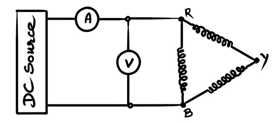
Whatever may be the method, we connect the measuring leads across the phase and neutral terminals for a star-connected winding, as shown.
Between the red (R) phase terminal and neutral (N), we get the resistance of the red phase winding.
Similarly, between the blue (B) phase terminal and neutral (N), we get the resistance of the blue phase winding.
Between the yellow (Y) phase terminal and neutral (N), we get the resistance of the yellow phase winding.
Delta Connected Winding
However, in the case of a delta-connected winding, no separate neutral is available. Therefore, we have to measure the resistance between two phases. However, the resistance obtained is not the actual resistance of a single winding. This is because, the measurement includes one winding in parallel with the other two windings connected in series. Therefore, whatever resistance value we obtain must be multiplied by 1.5 to get the actual resistance of a single winding.
If you see the diagram, you can understand this clearly. Suppose we are measuring the resistance between the red and yellow phases. Across these two terminals, there will be another path consisting of the other two windings connected in series. Therefore, the measured resistance will be the equivalent resistance of the entire network between the two terminals. Hence, we have to multiply the measured value by a factor of 1.5 to obtain the actual resistance of a single winding.
How does this factor 1.5 come? We are not going to discuss here. It is very simple. If you perform the circuit analysis of the delta-connected winding, you will find that the actual winding resistance is 1.5 times the measured resistance.
Temperature Correction
Then, we correct the measured resistance for the temperature of 75°C. For that, we need to know the winding temperature at the time of measurement.
So, what do we do? We keep the transformer de-energized for at least three (3) hours before measuring the resistance. Then, we measure the top oil temperature and bottom oil temperature by placing sensors in the top and bottom oil pockets of the transformer. By taking the average of these two temperatures, we obtain the average oil temperature that is, \[\frac{\text{Top Oil Temperature + Bottom Oil Temperature}}{2}\]
We consider this average oil temperature as the winding temperature. This is because the transformer has remained de-energized for a sufficiently long period. That is more than 3 hours. When the temperature difference between the top oil and bottom oil becomes less than 5°C, only then we proceed for the resistance measurement.
We then apply the following formula to calculate the corrected resistance.
\[R_{75} = R_{T}\frac{235 + 75}{235 + T}\]
Where, \(R_T\) is the measured resistance at T°C, and \(R_{75}\) is the resistance corrected to 75°C.
Necessity of Winding Resistance Measurement Test of a Power Transformer
This measured resistance tells us about the integrity of the winding. It helps to determine whether there is any loose connection, broken conductor, or abnormal high-resistance joint in the winding. If everything is in order, the measured value remains within the specified limits.
Resistance measurement is also important because, from the measured DC resistance, we can directly calculate the rated load loss of the transformer and compare it with the value obtained during the load loss test. Furthermore, during the temperature rise test, we require the measured resistance for calculating the winding temperature.