Surge impedance loading, or SIL, is the quantity of power in MVA that a transmission line can carry most efficiently. For understanding the basic concept of surge impedance loading, first, we have to understand the effect of reactive power in a transmission line. How does it reduce the efficiency of the transmission system? The expression of real power is. Additionally, the expression of reactive power is . If reactive power increases, also increases. In other words, the phase angle between the voltage and current of the transmission line increases. At the same time, decreases, so real power decreases.
Voltage Drop in Transmission Lines Increases
To keep real power constant, the system absorbs more current from the source. Therefore, the line current increases. Because the system voltage remains nearly constant. Now, voltage regulation is given by the difference between the sending-end voltage and the receiving-end voltage. That is,
If the system tries to keep real power constant, the current increases. Also, due to increased , the term increases. The value of X is much greater than the value of R in a transmission line. So the overall voltage drop across the line increases. That is one of the major problems of high reactive power.
Efficiency of Transmission Lines Decreases
Now, come to line loss. We have already mentioned the current increases for increasing reactive power. Therefore, loss (ohmic loss) also increases. Obviously, this reduces transmission efficiency.
Surge Impedance Loading Calculation
But if 𝜙 becomes zero, the current is minimum for the same power. As a result of that condition, both the ohmic loss and voltage drop of the line become minimum. So, we have to estimate the condition at which the phase angle between current and voltage is zero. It means there is no reactive power flowing through the transmission line.
Mathematical Derivation of Surge Impedance Loading
Here, XL is the inductive reactance of the transmission line. Whereas, XC is the shunt capacitive reactance of the transmission line. The term represents inductive reactive power. Similarly, represents capacitive reactive power. Here, I is the line current, and V is the system voltage.
The transmission line absorbs inductive reactive power and generates capacitive reactive power. If these two powers are equal in magnitude, then generation and absorption are balanced. Hence, there will be no net reactive power in the system. To satisfy that condition, we can write
From here, we can write
or
The reactance expressions are,
Where L is the series inductance per unit length, and C is the shunt capacitance per unit length of the transmission line. l is the total length of the transmission line. From here, we get
Therefore,
This gives
Hence,
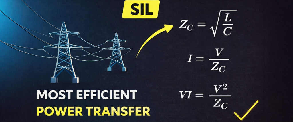
This is called the surge impedance. Obviously, from equation (i), we can also write
As the system voltage is approximately constant. Additionally, and L is the inductance per unit length, and C is the capacitance per unit length. Since both L and C are constant, is also constant. Therefore, the current I becomes fixed. Only at this current does the transmission line perform more efficiently without excessive power loss and voltage drop. Now, if we multiply the system voltage (V) on both sides of the equation (ii), we get
VI is called surge impedance loading, which is the loading at which the transmission line performs most efficiently.