
The fault calculation is an essential part of power-system analysis. Because it determines the short circuit rating of different electrical components used in the power system. We also design protective-relaying schemes based on the fault levels. For example, a circuit breaker must be capable of making and breaking the fault currents. Additionally, it must withstand adequate short time current during a fault. All other components of a power system must also withstand the short time fault current.
For fault level calculations, always consider a three-phase fault. Because, a three-phase fault produces the maximum fault current is each phase. For steady-state fault calculations we consider the steady-state reactance of the system. Additionally, we take the rms value of fault current and voltage. For, simplicity, we neglect resistance and capacitance of the system.
The fault calculation gives us the fault current levels at different points of a power system. We can also express the fault in the form of apparent power. We can represent the apparent power, or MVA, at any point in the system as\[MVA_n = \sqrt{3}VI\]Where V represents phase-to-phase voltage in kV (RMS). Alos, ‘I’ implies normal current in kA (RMS). Thus, \(MVA_n\) provides the normal apparent power.
Fault MVA
Say, during a three-phase fault the current increases to fault current \(I_f\). Therefore, the MVA associated with the fault becomes\[\text{Fault MVA}_f = \sqrt{3}VI_f\]The fault current, \(I_f\) kA rms, lags the voltage by \(90^\circ\). During a fault the load side becomes almost short circuited. Therefore, the system reactance up to the fault point controls the current flowing into the fault. Fault current generally reaches several times the normal current with \(90^\circ\) lag.
Typical Fault Currents
| Nominal Voltage (line-to-line), kV | Steady-State Fault Level, kA rms |
|---|---|
| 11 | 25 |
| 33 | 25 – 31.5 |
| 132 | 31.5 – 40 |
| 220 | 40 – 50 |
| 400 | 20–40 |
As utilities add generation capacity and new interconnections, fault levels increase at different points in the power system.
Procedure of Fault Calculations
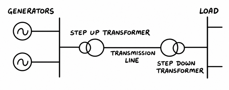
- Draw the system diagram. We begin by drawing a single-line diagram of the given power system.
- Select base values. Then we choose suitable kV and MVA base values for each voltage level.
- Calculate base quantities. Using the selected bases, we calculate the base current and base impedance at each voltage level.
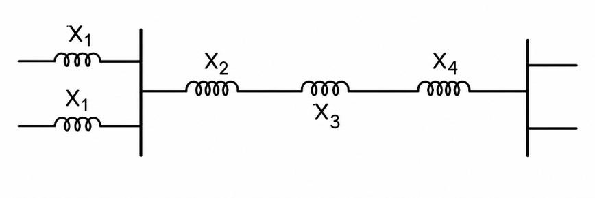
- Develop the network diagram. Then we draw the reactance diagram of the system.
Classification of Faults
We adopt the per-unit system for fault calculations. Because it simplifies the analysis. We can represent a balanced three-phase system as a single-phase system having one phase and a neutral. In the diagram, we draw the components of the system with their symbols.
Then we draw the reactance diagram replacing the symbols of the equipment with their internal per unit reactance.
Video on fault calculation in Power System
Per Unit Method
Engineers often express voltage \((V)\), current \((I)\), MVA, and impedance \((Z)\)as a percentage or per-unit (p.u.) value of a selected base quantity. The per-unit method simplifies power-system calculations.
We define a per-unit quantity as, \[\text{Per-unit value} =\frac{\text{Actual value}}{\text{Base value}}\]For example, suppose we choose 132 kV as the base voltage. Then 132 kV represents 1 pu or 100%. Therefore,\[33\,kV = \frac{33}{132} = 0.25\text{ pu} = 25\%\]and\[66\,kV = \frac{66}{132} = 0.5\text{ pu} = 50\%\]We can express other quantities such as current (I) and impedance (Z) in the same way using their respective base values. For example, if we choose 218 A as the base current,\[874\,A = \frac{874}{218} = 4\text{ pu}\]and\[218\,A = \frac{218}{218} = 1\text{ pu}\]
Selecting the Base Quantities
We should initially select only two base quantities. Then we calculate the remaining base quantities from these two base quantities. Because kV, MVA, (I), and (Z)are interrelated and must satisfy Ohm’s law. For fault levels calculation we generally select Base kV and Base MVA. Then we calculate the base current (I)and the base impedance (Z) from them. For a power transformer, we choose the same MVA base on both sides of the transformer. The we choose the base kV value for HV and LV side equals to the transformer voltage ratio.
\[\frac{\text{Base kV}_1}{\text{Base kV}_2}=\frac{\text{Transformer kV}_1}{\text{Transformer kV}_2}\]When we select the base voltages this way, the transformer has the same per-unit reactance when referred to either side of the transformer. Therefore, for a system containing transformers, we keep the base MVA the same throughout the system. Then, change the base kV according to each the voltage ratio of each transformer. Obviously, this greatly simplifies per-unit calculations in power systems.
Per Unit Voltage
First, we calculate the per-unit voltage as\[\text{p.u. kV} =\frac{\text{Actual kV}}{\text{Base kV}}\]
Base Current
Second, we calculate the base current as\[I_{\text{base}} =\frac{\text{Base MVA}}{\text{Base kV}}\text{ Amperes}\]
Base Impedance
Then, we calculate the base impedance from the base voltage and base current as,\[Z_{\text{base}} =
\frac{\text{Base kV} \times 1000}{I_{\text{base}}}\ \Omega\]Substituting the expression for base current, we get,\[Z_{\text{base}}=\text{Base kV}\times\frac{\text{Base kV}}{\text{Base MVA}}\times 1000\]Therefore, we can write,\[Z_{\text{base}}=\frac{(\text{Base kV})^2 \times 1000}{\text{Base MVA}}\ \Omega\]
Per Unit Impedance
Then we calculate the per-unit impedance by dividing the actual impedance by the base impedance, \[Z_{\text{p.u.}}=\frac{Z_{\text{actual}}}{Z_{\text{base}}}\]Substituting the expression for \(Z_{\text{base}}\), we get,
\[Z_{\text{p.u.}}=Z_{\text{actual}}\times\frac{\text{Base kVA}}{(\text{Base kV})^2 \times 1000}\]