
We shall discuss the construction, uses and working principle of a potentiometer.
Errors in Voltmeters
Whenever we connect a voltmeter between two points of a circuit, it takes a shunt current depending on its internal resistance. Ideally, the internal resistance of a voltmeter is infinite. However, practically, this resistance is very high but not infinite. Therefore, as soon as we connect a voltmeter across a part of a circuit, some current passes through the voltmeter. As a result, the actual voltage drop across that part of the circuit becomes a little bit reduced. Therefore, the measurement of voltage across that portion of the circuit becomes erroneous.
What is a Potentiometer?
A potentiometer is such a device which can measure the voltage without taking any current from the measuring circuit. Therefore, the measurement becomes nearly 100% accurate.
Construction
A potentiometer mainly consists of a long metal wire of uniform cross-section. In a potentiometer, normally we fix that metal wire on a wooden platform. Actually, we place standard 1 m long wires in parallel. Then we connect these wires one by one in series with thick copper bars to nullify the interconnection resistance between the 1 m long wires. Then we connect this series arrangement of 1 m long wires across a battery along with a rheostat. We refer to this as the driving circuit of the potentiometer.
Now, by adjusting the rheostat, we supply a constant current to the wires of the potentiometer. As a result, a voltage drops across the whole wire. We use such a number of 1 m long wires in a potentiometer; the total length of the wires in series becomes 5 to 10 meters, depending upon the design requirement. The wooden platform has its own scale printed beside the wires. Therefore, each length of the wires gives the voltage corresponding to its length. This is because the wire is uniform. Hence, it gives a uniform voltage drop along its length. Now, we attach one sliding contact on the potentiometer wires.
Voltage Measuring Principle of the Potentiometer
We connect the fixed contact of the potentiometer wire with one end of the measuring circuit. Then we connect the other end of the measuring circuit to the sliding contact of the potentiometer through a galvanometer.
Now, the voltage of the measuring circuit does not equal the voltage drop across the wire between the fixed and sliding contacts. As a result, a current flows through the galvanometer. Now, we adjust the length of the potentiometer wire with the help of the sliding contact. Suppose, at a certain position of the sliding contact, the galvanometer shows null deflection.
As the galvanometer shows null deflection, there is no current flowing between the measuring circuit and the potentiometer wires. This also implies that there will be no potential difference between the measuring circuit and the potentiometer wires.
Now, we can easily predict the voltage drop from the active length of potentiometer wire. The active length is the length of the potentiometer wire between the position of the sliding contact and fixed contact. We can easily measure the active length of the wire from the scale printed on the wooden platform. Therefore, the potentiometer gives the voltage across the measuring circuit without taking any current from it.
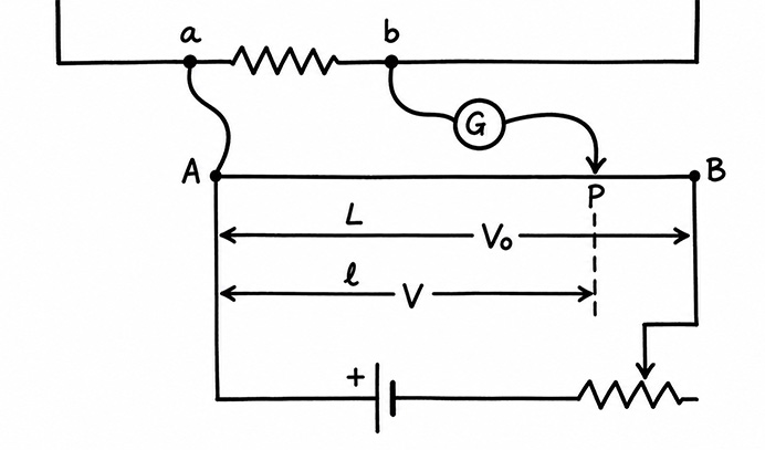
Suppose, AB is the total length of the potentiometer wire. P is the position of the sliding contact for which the galvanometer shows null deflection. Now, ab is the part of the circuit where we are measuring the voltage. As a and A are connected using a thick copper or silver wire, the potential of these two points remains the same under all conditions. At null deflection condition of the galvanometer, the potential of point b becomes equal to the potential of point B. Therefore, length AP shows the voltage across ab.
Working Principle of Potentiometer
Suppose, the driving circuit establishes a potential difference \(V_0\) across the entire length of the potentiometer wire AB. The total length of the wire AB is \(L\) meters. Therefore, the voltage developed per unit length of the wire is,
\[\frac{V_0}{L}\text{ volt/meter}\]
Now, at balanced condition, the length of the active wire AP is \(l_1\) meters. Therefore, the measured potential difference between a and b of the measuring circuit is,
\[\frac{V_0}{L}\times l_1\text{ volts}\]
Comparison of EMFs of Two Battery Cells
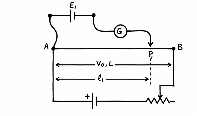
Here, we connect one battery cell between the fixed and sliding contacts of the potentiometer. Now, we adjust the jockey or sliding contact to make the null deflection in the galvanometer. Say, \(P_1\) is the point for which the galvanometer shows the null deflection.
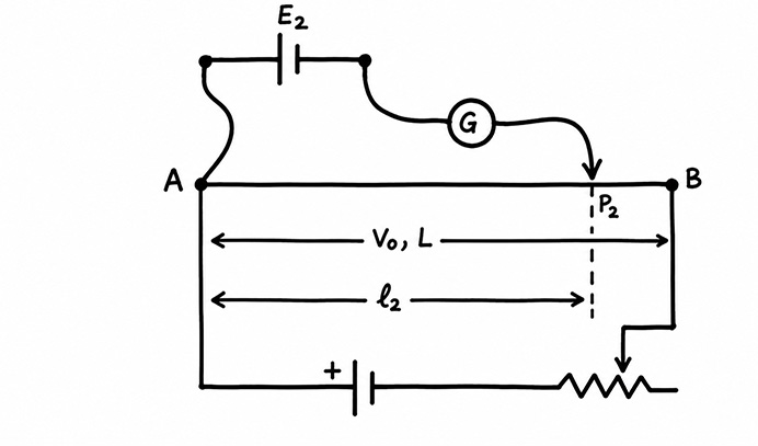
Then, we replace the first battery cell with the second battery cell. Again, we adjust the position of the sliding contact for which the galvanometer gives null deflection. Now, the new position of the sliding contact becomes \(P_2\).
Consider,
\[AB=L\text{ meter,} \]\[AP_1=l_1\text{ meter,} \]\[AP_2=l_2\text{ meter}\]
Now, the potential of the battery cell 1 is,
\[E_1=\frac{V_0}{L}\times l_1 \qquad …(1)\]
Similarly, the potential of the battery cell 2 is,
\[E_2=\frac{V_0}{L}\times l_2 \qquad …(2)\]
By dividing (1) by (2), we get,
\[\boxed{\frac{E_1}{E_2}=\frac{l_1}{l_2}}\]
Measurement of Internal Resistance of a Battery
Say, the emf of the measuring battery cell is \(E\). The internal resistance of the cell is \(r\). Now, we connect a known resistance \(R\) across the battery with a switch (S). Now, we connect this entire arrangement across the fixed and sliding contact of a potentiometer as shown.
Measurement Keeping the Switch (S) Open
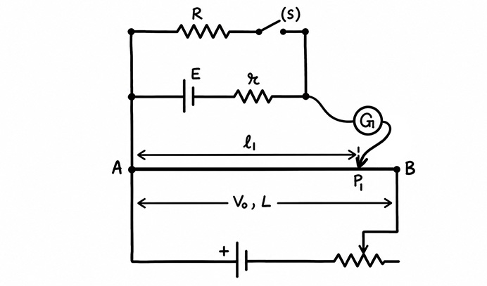
Here, we adjust the position of the sliding contact for null deflection of the galvanometer. At the balanced condition, the active length of the potentiometer wire becomes \(AP_1=l_1\) meter. Therefore, as per the principle of the potentiometer, the emf of the battery becomes,
\[E=\frac{V_0}{L}\times l_1\]
This is because, as we keep the switch (S) open, at balanced condition, no current flows through the battery.
Measurement after Closing the Switch (S)
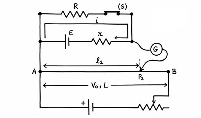
After that, we close the switch (S). As soon as we close the switch, current starts flowing through the battery cell. As a result, the potential across the battery decreases due to the internal resistance of the battery. Obviously, this disturbs the balance condition of the circuit and the pointer of the galvanometer deviates from the null position.
Therefore, we need to adjust the sliding contact of the potentiometer again. After adjustment, at the new position of the sliding contact, again the galvanometer gives null deflection on its dial. Say, this new position of the sliding contact is \(P_2\). Also, the length \(AP_2\) is \(l_2\) meters (say). So, the new voltage that appears across the battery is,
\[V=\frac{V_0}{L}\times l_2\text{ volt}\]
At balanced condition, the potentiometer is not taking any current from the battery. However, a current circulates in the closed circuit formed by the battery and the resistance \(R\). Obviously, this current will be,
\[i=\frac{E}{R+r}\]
The voltage drop across the resistance \(R\) is \(iR\) volts, as
\[iR=\frac{ER}{R+r}\text{ volt}\]
Obviously, this is nothing but the measured voltage \(V\). Therefore, we can write,
\[V=iR=E-ir=\frac{ER}{R+r}\]
Now,
\[V=\frac{V_0}{L}l_2=\frac{V_0}{L}l_1\frac{R}{R+r}\]
Therefore,
\[l_2=\frac{l_1R}{R+r}\]\[Rl_2+rl_2=l_1R\]\[\boxed{r=\frac{R(l_1-l_2)}{l_2}}\]
We know the value of the known resistance \(R\). Also, we know the value of \(l_1\) and \(l_2\). So, easily we can calculate the internal resistance \(r\) of the battery cell.