Cause of Voltage Regulation
Every electrical source has some internal or inherent impedance. It may be a battery, a transmission line, a power transformer, or any other device that can supply electric power. Due to this inherent impedance, there is always a voltage drop in that system. When we measure the voltage across the open output terminals of, we find a voltage. But when we connect the load current starts flowing. Hence, there will be a voltage drop. Due to this voltage drop, the output terminal voltage reduces somewhat. This causes the voltage regulation.
Definition of Voltage Regulation
We define the voltage regulation as the change in terminal voltage from no-load to full-load condition, expressed as a percentage of the rated full-load voltage. Therefore, mathematically, we can express as
\[\text{% Voltage Regulation} = \frac{V_2(NL) – V_2(FL)}{V_2(FL)}] × 100\%\]
Where
- \(V_2(NL)\) = Terminal voltage at no-load
- \(V_2(FL)\) = Terminal voltage at full-load
Definition of Voltage Regulation of a Transformer
Alternatively, we can express the voltage regulation of a transformer as
\[\text{% Voltage Regulation} = \frac{E_2 – V_2}{V_2} × 100\%\]
Where
- \(E_2\) = Induced EMF in secondary winding,
- \(V_2\) = Secondary terminal voltage under full load.
Good voltage regulation of a transformer means a small percentage value. Obviously, a small voltage regulation indicates that the output voltage remains relatively constant from no-load to full-load conditions. Although ideally, a transformer should have zero voltage regulation. In other words, the terminal voltage remains constant regardless of the load.
Reasons for Voltage Regulation in a Power Transformer
Voltage regulation occurs in transformers due to several inherent characteristics. The transformer windings possess both resistance (R) and leakage reactance (X). When current flows through these impedances under load, there is a voltage drop that reduces the terminal voltage.
Vector Diagram Analysis
Understanding the Phasor Diagram
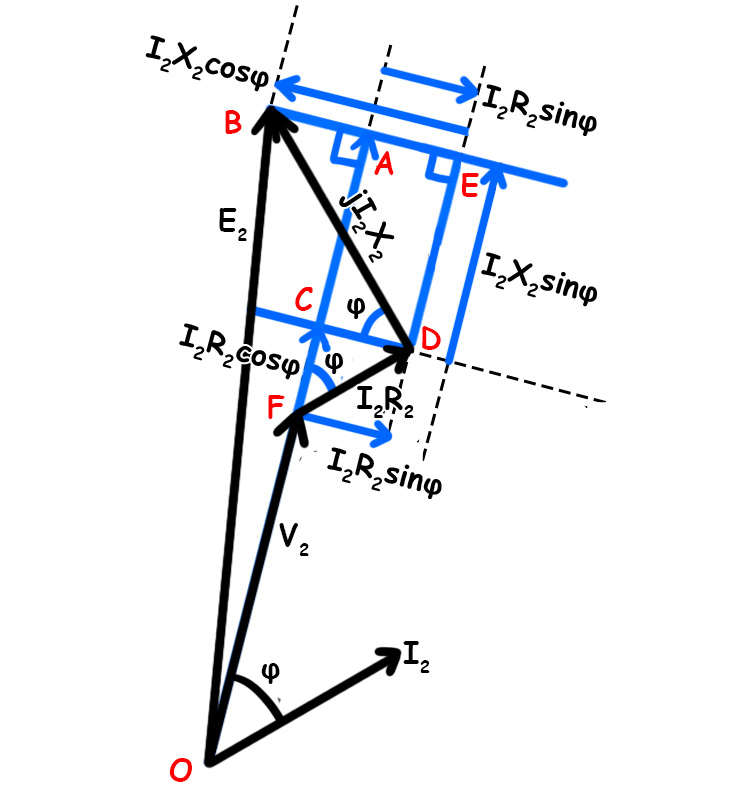
Firstly, let us identify what we are looking at. The diagram shows a transformer phasor diagram with current \(I_2\) at the reference angle. The voltage \(V_2\) represents the full-load secondary terminal voltage. Meanwhile, \(E_2\) represents the no-load secondary terminal voltage.
Setting Up the Geometry
The phasor diagram creates a triangle. Point O sits at the origin. Whereas, point A lies at the end of \(V_2\) line. Point B marks the end of \(E_2\).
Now, let us break down the current components. The load current \(I_2\) splits into two parts:
- \(I_2\cos\varphi\) acts in phase with \(V_2\)
- \(I_2\sin\varphi\) acts perpendicular to \(V_2\)
Constructing the Voltage Drops
Next, we add the voltage drops. The resistive drop \(I_2R_2\) acts parallel to the current. The reactive drop \(I_2X_2\) acts perpendicular to the current.
From the diagram, we can identify key segments:
- FC = \(I_2R_2\cos\varphi\) — This is the horizontal component of the resistive drop
- FD = \(I_2R_2\) — This is the total resistive drop
- AE = \(I_2R_2\sin\varphi\) — This is the vertical component of the resistive drop
- EB = \(I_2X_2\cos\varphi\) — This is the horizontal component of the reactive drop
Finding the Vertical Distance AB
Now we calculate AB. Obviousely, this equals EB minus EA. AB = EB – EA. Substituting the expressions
\[AB = I_2 X_2 \cos\varphi \,-\, I_2 R_2 \sin\varphi\]
Finding the Horizontal Distance OA
Next, we find OA.
\[OA = OF + FC + CA\]
Breaking this down further
- \(OF = V_2\)
- \(FC = I_2 R_2 \cos\varphi\)
- \(CA = DE = I_2 X_2 \sin\varphi\)
Therefore
\[OA = V_2 + I_2 R_2 \cos\varphi + I_2 X_2 \sin\varphi\]
Pythagorean Theorem
Since we have a rightangle triangle \(\Delta OAB\), we apply the Pythagorean theorem
\[E_2 = OB = \sqrt{OA^2 + AB^2}\]
\[E_2 = \sqrt{(V_2 + I_2 R_{2} \cos\varphi + I_2 X_{2} \sin\varphi)^2 + (I_2 X_{2} \cos\varphi – I_2 R_{2} \sin\varphi)^2}\]
This represents the no-load voltage in terms of the full-load voltage and the voltage drops.
Voltage Regulation Formula
Finally, we can define the voltage regulation of a transformer as
\[\text{Voltage Regulation} = \frac{E_2 – V_2}{V_2} \times 100\%\]
This formula tells us how much the voltage changes from no-load to full-load conditions. A smaller value indicates better regulation. The expression derived here allows us to calculate \(E_2\) using the full-load parameters, which then gives us the voltage regulation.
The key insight is this: we’ve transformed the geometric phasor relationships into an algebraic expression that captures how resistance, reactance, current, and power factor affect voltage regulation.
The vector diagram for voltage regulation depends on the power factor of the load. For Lagging Power Factor (Inductive Load)
Approximation of Voltage Regulation of a Transformer
For practical transformers, the angle between \(E_2\) and \(V_2\) is small. So, the component perpendicular to \(V_2\) is very small. Hence, the perpendicular component is negligible. Hence,
\[E_2 \approx V_2 + I_2 R_{2} \cos\varphi + I_2 X_{2} \sin\varphi\]
Therefore, the voltage drop is
\[E_2 – V_2 = I_2 R_{2} \cos\varphi + I_2 X_{2} \sin\varphi\]
\[\Rightarrow E_2 – V_2 = I_2 (R_2 \cos\varphi + X_2 \sin\varphi)\]
Voltage Regulation Formula
\[\text{% Voltage Regulation} = \left( \frac{E_2 – V_2}{V_2} \right) \times 100\]
\[\Rightarrow
\text{% VR} = \left[ \frac{I_2 (R_{2} \cos\varphi + X_{2} \sin\varphi)}{V_2} \right] \times 100\]
In per-unit or percentage form
\[\text{% VR} = \left( \frac{I_2}{I_{2(\text{rated})}} \right)
\left( \frac{R_{2} \cos\varphi + X_{2} \sin\varphi}{V_2} \right) \times 100\]
At full load \(I_2 = I_2 (Rated)\), hence
\[\text{% VR} = \left( \frac{R_{2}}{V_2} \cos\varphi + \frac{X_{2}}{V_2} \sin\varphi \right) \times 100\]
\[\Rightarrow \text{% VR} = \%R \cos\varphi + \%X \sin\varphi\]
Here,
\[\%R = \left( \frac{I_2 R_{2}}{V_2} \right) \times 100\]
\[\%X = \left( \frac{I_2 X_{2}}{V_2} \right) \times 100\]
Voltage Regulation for Leading Power Factor
- \(\% VR = \%R cos\varphi \,- \,\%X sin\varphi\)
- Can be negative (voltage rise), meaning load coltage > no load voltage
Factors Affecting Voltage Regulation
Load Power Factor
This is the most significant factor affecting voltage regulation:
- Lagging power factor (inductive loads) produces the highest positive regulation. Both resistance and reactance drops add together, causing maximum voltage drop.
- Unity power factor (resistive loads) produces moderate regulation.Because only the resistive component contributes to the voltage drop here.
- Leading Power Factor (Capacitive loads): Produces low or negative regulation. The capacitive reactive drop opposes the resistive drop, reducing the net voltage drop. At a specific leading power factor, regulation can be zero or even negative (voltage rise under load).
Load Current Magnitude
The voltage regulation of a transformer also increases with increasing load current. As the load increases, both IR and IX drops increase.
Transformer Impedance (R and X)
- Higher winding resistance: Increases regulation, especially at unity and lagging power factors. Larger conductor cross-sections reduce R and therefore improve regulation.
- Higher leakage reactance: Significantly increases regulation at lagging power factors, but can improve regulation at leading power factors. The leakage reactance depends on winding configuration, spacing, and core geometry.
- Impedance ratio (X/R ratio): Typical power transformers have X >> R. Hence, this makes reactance the dominant factor. Therefore, a high X/R ratio makes the transformer more sensitive to power factor variations.
Transformer Design Features
- Core type vs. Shell type: Shell-type transformers generally have lower leakage reactance due to better magnetic coupling, resulting in better regulation.
- Winding arrangement: Interleaved or sandwich windings reduce leakage reactance and improve regulation compared to concentric windings with large separation.
- Core material and design: High-quality core materials with low reluctance reduce leakage flux and improve regulation.
Transformer Rating and Size
- Larger transformers generally have better (lower) percentage regulation because the impedance drops constitute a smaller percentage of the rated voltage.
- Higher voltage ratings also tend to have better regulation as the percentage impedance is typically lower.
Operating Temperature
- Obviously, winding resistance increases with temperature (approximately 0.4% per °C for copper).
- Full-load regulation is slightly higher than the calculated value due to the temperature rise.
- This effect is usually small (1-2%) but becomes significant in poorly cooled transformers.
Frequency
- Leakage reactance (X = 2πfL) is directly proportional to frequency.
- Therefore, Higher frequency increases the reactive drop and worsens the regulation.
- This is generally not a concern for power transformers operating at a constant 50/60 Hz.
Transformer Loading History
- Transformer impedance can slightly change with loading history due to mechanical forces on windings.
- Also, short-circuit events can permanently alter leakage reactance.
- In addition, aging and insulation degradation may affect regulation over decades of operation.