
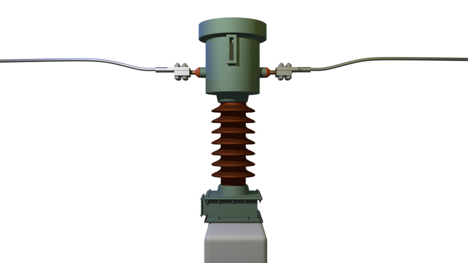
A live tank current transformer (Live Tank CT) is a high-voltage current transformer. Here we place the entire current transformer at the top of the device. If we imagine a current transformer, the primary of the current transformer is nothing but the line conductor. Because of that, we connect the primary in series with the line. Now, the core of the current transformer surrounds this live line, and this core holds the secondary winding on it. So whenever current flows through that line, there will be a flux linkage with the core, and that flux will produce an induced current in the secondary winding.
The terminals of the secondary winding come down at the bottom, where we can connect the external metering or relaying circuit. So this is the entire CT. A live line holds a secondary ring-like core with winding surrounding the live line, and this is nothing but the current transformer. Now, this is the very basic structure of a live tank current transformer.
Why do we call it a live tank current transformer?
If we examine the constructional details of the live tank current transformer, we can easily understand why it is called a live tank current transformer.
Construction of a Live Tank Current Transformer
Primary Winding of a Live Tank CT
The primary of a live tank current transformer is either a conducting rod or a flexible stranded copper conductor, or any similar type. There are two styles. Either it runs continuously from one side to the other side of the current transformer. The thick primary conductor inside the transformer connects and bridges the opposite side studs of the current transformer.
Core a Live Tank CT
The iron core, normally of ring shape, surrounds the primary conductor. Normally, manufacturers use cold-rolled grain-oriented silicon steel as the core material. Because cold-rolled grain-oriented silicon steel reduces hysteresis loss. Additionally, the core is laminated. Also, the laminations are coated with enamel varnish. Because this increases the resistance between the laminations. Therefore, the varnish-coated laminations reduce eddy current in the core. Normally, manufacturers provide a layer of electrical-grade insulation paper to cover the cores.
Sometimes, instead of cold-rolled grain-oriented silicon steel, manufacturers also use nanocrystalline cores for the purpose. Nanocrystalline core material is a modern type of core material used for better accuracy in current transformers.
Secondary Windings a Live Tank CT
The manufacturer then wraps secondary copper wire on the core to construct the secondary winding. They use iron varnish, enamel single-strand copper wires. Alternatively, they also use paper-insulated or paper-covered single-strand copper wire for the winding. Paper-insulated copper wire is more ideal for the purpose.
For an oil-immersed live tank current transformer, the number of turns of the secondary winding depends on the current ratio.
Secondary Terminals of a Live Tank CT
For a single-ratio current transformer, only two terminals come from the two extreme ends of the winding. But for a multi-ratio current transformer, intermediate tapping terminals also come out.
Suppose the live tank current transformer has a ratio of 200/1 A. Then only two terminals will come out from the secondary winding. We normally denote these two terminals as 1S1 and 1S2. Here, the first digit “1” denotes the serial number of the core, and the last digit implies the beginning or end terminal of the winding. 1S1 means the first secondary terminal of the first core. On the other hand, 1S2 means the second secondary terminal of the first secondary core.
Now, if the ratio of that current transformer is 400–200/1 A, there will be three terminals coming out from the winding. We name these terminals as 1S1, 1S2, and 1S3. When we need the ratio 200/1 A, we use secondary terminals 1S1 and 1S2. Again, when we need the current ratio of 400/1 A, we simply use the terminals 1S1 and 1S3.
The secondary terminals come down to the secondary terminal box placed at the bottom of the current transformer. The manufacturer covers the secondary core winding assembly along with the terminal leads with electrical-grade paper.
Live Tank and Insulator Housing
Now, an iron tank covers the entire current transformer at the top except for the leads. The secondary leads come down to the secondary terminal box at the bottom. The bottom iron container holds the secondary box as well as the supporting insulator of the current transformer.
Manufacturers normally use porcelain or polymer-made cylindrical hollow insulator housings with a sufficient number of weather sheds or rain sheds. The number and diameter of rain sheds or weather sheds are such that they provide the required minimum creepage distance. In normal areas, engineers prefer 25 mm/kV, whereas in very heavily polluted areas, they prefer 31 mm/kV creepage distance.
There is an inlet valve at the top of the tank and a drain valve attached to the bottom of the current transformer. The top valve is used to top up the insulating oil in the transformer. The drain valve is used to drain the oil if required. Manufacturers provide an oil level indicator on the live tank to view the actual level of the oil. So, we preferably place the oil level indicator a little above the stud level of the header tank.
Stud and Insulator a Live Tank CT
Manufacturers normally use a small insulator to isolate the tank from the stud terminal at least at one end. Whereas, the other end can be in contact with the tank. This small insulation prevents the primary current from bypassing through the tank body. Since the voltage of the primary terminals is equal to the live tank, there is no need to provide heavy insulation between the primary and the header tank. If we remove the small insulator, the current will bypass through the tank. As a result, the live tank current transformer provides erroneous measurements.
Pressure Release Valve
At the top of the tank, there is a pressure release valve. This valve activates to release high pressure generated during any abnormal condition of the current transformer. In the event of any unwanted situation, this valve releases the hot oil through it. Therefore, it prevents unnecessary blasting of the current transformer during such conditions.
Normally, manufacturers provide a cap-like cover on the top of the tank to give a better aesthetic look.