An induction disc relay is a variety of electromagnetic relays. It belongs to one of the most primitive forms of conventional electromechanical protection relays. Its basic construction and working principle are quite simple.
Basic Construction of Induction Disc Relay
There is an electromagnet. The system current or a current proportional to the system current flows directly through the coil of the magnet. As a result, the alternating current flowing through the coil produces alternatingly changing magnetic flux in the core of the electromagnet.
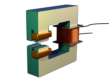
We specially design the core of the magnet to split the flux into two parts. Essentially, one limb of the magnetic core is divided into two poles. These two poles split the flux.
Splitting of Flux
One of the poles of the magnetic core is covered with a copper ring. We sometimes refer to it as a shading ring. Therefore, this pole is referred to as the shaded pole. When magnetic flux passes through the shaded pole, it induces a circulating current in the copper ring. This current produces a counterflux in the pole. Obviously, that flux opposes the main flux through that pole. Therefore, the main flux through the shaded pole lags behind the flux of the unshaded pole. As a result, it creates a phase difference between the flux of the shaded and the unsheathed pole.
Aluminum Disc
Then we place a circular lightweight aluminum disc between the faces of the electromagnet. The edges of the disc intercept the fluxes from both the shaded and unshaded poles. Since both fluxes are alternatingly changing in nature, they induce their respective eddy currents in the disc.
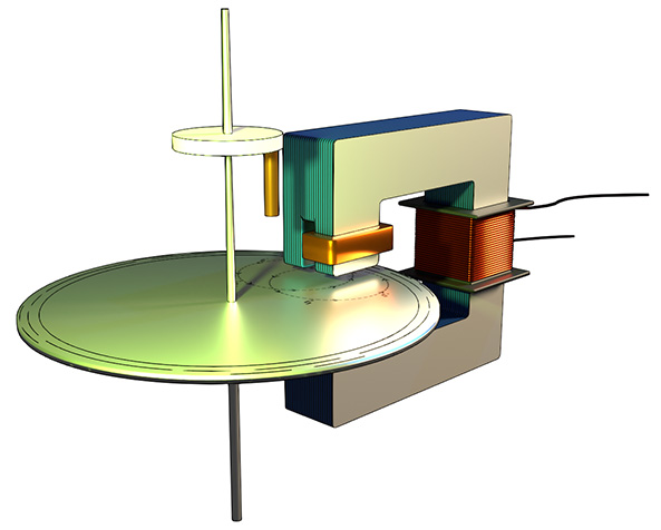
The eddy current produced by the unshaded pole interacts with the flux of the shaded pole. On the other hand, the eddy current produced by the shaded pole interacts with the flux of the unshaded pole. As a result of these interactions between the eddy currents and the magnetic fluxes, mechanical forces are produced on the disc on both sides. By applying Fleming’s Left-Hand Rule, we can determine the direction of these forces. The resultant force creates a torque that rotates the disc about its central spindle and bearings.
Restoring Force in Induction Disc Relay
A flat spiral spring attached to the spindle provides the necessary restoring force. When the disc rotates due to torque, the spring deforms and opposes the rotation. This restoring force prevents disc rotation under normal current conditions.
When the current exceeds a threshold value, the torque acting on the disc overwrites the restoring force, causing the disc to rotate. The spindle holds a moving contact, allowing it to rotate along with the disc. After a certain angle of rotation, the moving contact makes contact with the fixed contact, thereby closing the normally open (NO) contact.
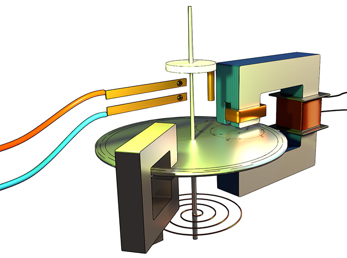
Damping in Induction Disc Relay
Damping is provided using a permanent magnet. As the disc rotates, it cuts the magnetic field of the permanent magnet, inducing eddy currents in the disc. According to Lenz’s Law, these eddy currents oppose the disc’s motion, introducing damping and preventing oscillations.
Torque in an Induction Disc Instrument
First, let us define the two flux components. We have the first flux as \(\phi_1 = \phi_m \sin(\omega t)\). Similarly, we have the second flux as \(\phi_2 = \phi_m \sin(\omega t – \theta)\). Here, \(\phi_m\) represents the maximum flux. Meanwhile, \(\omega\) is the angular frequency. Additionally, \(\theta\) is the phase angle between the two fluxes.
Next, we need to find how these fluxes change with time. Therefore, we differentiate both fluxes with respect to time. For the first flux, we get: \[\frac{d\phi_1}{dt} = \phi_m \omega \cos(\omega t)\]Similarly, for the second flux, we obtain: \[\frac{d\phi_2}{dt} = \phi_m \omega \cos(\omega t – \theta)\]
Torque Expression in Induction Disc Relay
Now, let us look at the torque in the system. The torque (T) is directly proportional to a specific combination. This combination is \((i_1 \phi_2 – i_2 \phi_1)\). In other words: \[T \propto i_1 \phi_2 – i_2 \phi_1\]Here, \(i_1\) and \(i_2\) are the induced currents in the disc. Furthermore, the alternating flux has a significant effect. It induces an electromotive force in the disc. Let us call the first induced EMF as \(e_1\). This EMF is directly proportional to the rate of change of flux. Therefore, we can write: \[e_1 \propto \frac{d\phi_1}{dt}\]
Likewise, the second induced EMF \(e_2\) is proportional to: \[e_2 \propto \frac{d\phi_2}{dt}\]Moreover, the disc has a special property. It has no coil-like structure. As a result, it has very negligible inductance. Consequently, the currents are directly proportional to the EMFs. Thus, we can write: \[i_1 \propto e_1\] \[i_2 \propto e_2\]
Combining the Relations
Therefore, we can establish a direct relationship. The currents are proportional to the rate of change of flux: \[i_1 \propto \frac{d\phi_1}{dt}\] \[i_2 \propto \frac{d\phi_2}{dt}\]Subsequently, we substitute these into our torque equation: \[T \propto \frac{d\phi_1}{dt} \cdot \phi_2 – \frac{d\phi_2}{dt} \cdot \phi_1\]Now, let us expand this expression using our original equations. We substitute the values we found earlier.
For the first term: \[\frac{d\phi_1}{dt} \cdot \phi_2 = \phi_m \omega \cos(\omega t) \cdot \phi_m \sin(\omega t – \theta)\]For the second term: \[\frac{d\phi_2}{dt} \cdot \phi_1 = \phi_m \omega \cos(\omega t – \theta) \cdot \phi_m \sin(\omega t)\]After simplification, we get: \[T \propto \phi_m^2 \omega [\sin(\omega t – \omega t + \theta)]\]This simplifies further to: \[T \propto \phi_m^2 \omega \sin\theta\]However, \(\omega\) is constant. Therefore, we can write: \[T \propto \phi_m^2 \sin\theta\]
Relating to Input Current
Finally, let us connect this to the input current. We denote the input current to the relay as (I).
Importantly, the maximum flux is directly proportional to the input current: \[I \propto \phi_m\]
Consequently, we can substitute this relationship into our torque equation\[T \propto I^2 \sin\theta\]
Conclusion
Thus, an induction disc-type protection relay operates on the principle of a single-phase induction motor. The rotational speed of the disc (acting as the rotor) depends on the magnitude of the current injected into the operating coil of the electromagnet.
The torque is directly proportional to the square of the current. Additionally, it is proportional to the sine of the phase angle. This means two things. First, increasing the current increases the torque quadratically. Second, the phase angle between the split phases affects the torque produced significantly.