Here, in this post, we have discussed the DC Control Circuit of an SF6 Circuit Breaker.
Selective DC Supply for High‑Voltage Circuit Breakers
A circuit breaker’s control power always uses DC. In high‑voltage installations (132 kV and above), designers often choose a selective DC supply. In this scheme, two separate DC sources, Supply 1 and Supply 2, feed the DC control circuit of the breaker. When Supply 1 is healthy, its monitoring contactor (K12) remains energized. In that state, K12’s normally‑open contacts close and feed the DC control circuit from Supply 1. At the same time, its normally‑closed contacts open and isolate Supply 2.

If Supply 1 ever fails, K12 de‑energizes instantly. Its normally‑open contacts open, and its normally‑closed contacts close. This action automatically switches the breaker’s DC control circuit over to Supply 2, ensuring continuous DC power without manual intervention.
Trip Circuit of a DC Control Circuit
The main component here is the trip coil, which receives a DC pulse to operate the breaker. This coil is controlled by a set of auxiliary contacts and condition-based interlocks.
Auxiliary Switch of Circuit Breakers
One of these is a normally open (N.O.) contact of the breaker’s auxiliary switch. This contact remains open when the breaker is in the open position. There is also a normally closed (N.C.) contact, which stays closed when the breaker remains in the open condition. When the circuit breaker becomes closed, the N.O. contact closes, and the N.C. contact opens.
SF6 Lockout Contact
Another important contact in this path is the SF6 lockout contact. This contact monitors the gas pressure inside the breaker. If the SF6 pressure is at or above the required threshold, the contact remains closed, allowing normal operation. If the pressure drops below the lockout level, the contact opens, disabling the trip (also close) commands for safety.
Local Remote Selector Switch
The circuit also includes a local/remote selector switch. When the operator sets the switch to “REMOTE,” he can trip the CB from the control room. In the “LOCAL” position, the operator can manually trip the breaker using a push button or rotary switch on the breaker panel.
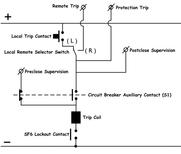
When the operator issues a trip command and all interlocks are in proper condition (i.e., the breaker is closed and SF6 pressure is healthy), the DC flows through the closed contacts in series with the trip coil. The DC energizes the trip coil, which then triggers the circuit breaker to trip either to isolate a fault or to carry out an operational requirement.
Pre-Close and Post-Close Supervision in Circuit Breakers
The above diagram shows the pre-close supervision terminal. It works when the circuit breaker is in the open condition. In this state, a specific auxiliary contact (NC) remains closed, allowing a supervision signal to be sent to the control panel. This indicates that the breaker is ready for closing. After the breaker closes, this same contact changes to open. This condition is now called post-close supervision. The signal path from the pre-close contact becomes open, meaning no supervision signal passes through it. Instead, another path, associated with the post-close supervision contact—provides the signal to indicate that the breaker is now closed.
Closing Circuit in DC Control Circuit
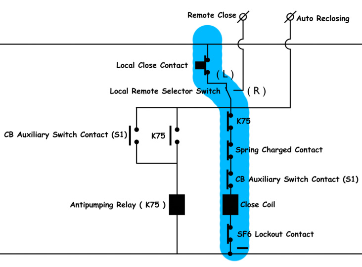
In an SF6 circuit breaker, the closing circuit operates using the positive bus of a DC control supply. A branch from the positive bus line connects to a contact of a push button or rotating closing switch. When the operator presses or activates this switch, voltage reaches the “LOCAL” terminal of the local/remote selector switch.
If the selector is set to “LOCAL” mode, the positive voltage flows through multiple interlocked contacts and reaches the closing coil.
These include a normally closed (N.C.) contact of the anti-pumping relay, a normally closed contact of the auxiliary switch of the circuit breaker, a closed contact of the spring charging mechanism, and a normally open (N.O.) contact of the SF6 general lockout relay.
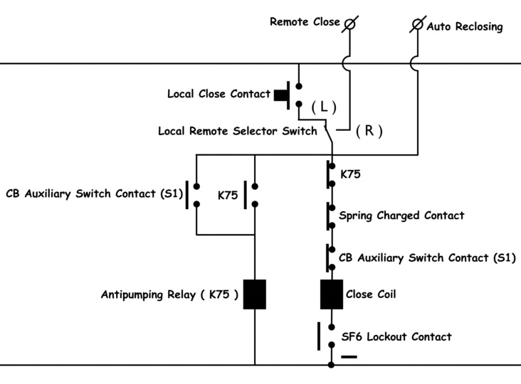
For the closing operation to take place, certain conditions must be fulfilled. The SF6 gas pressure must be normal, i.e., above the lockout level, to ensure proper insulation and arc-quenching. The anti-pumping relay must be in a de-energized state, keeping its contact closed. Additionally, the circuit breaker must be in the open condition, and the closing spring must be fully charged. When all these conditions are met and the local closing switch is operated, voltage reaches the closing coil, energizing it and causing the circuit breaker to close.
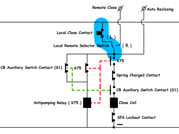
Anti-Pumping Mechanism in Circuit Breakers
Once the breaker closes, the auxiliary contact in series with the closing coil opens, stopping further voltage flow to the coil. Simultaneously, a normally open auxiliary contact closes and energizes the anti-pumping relay. This relay changes the state of its contacts: the N.O. contact closes, and the N.C. contact opens. As a result, the closing circuit is broken. This mechanism prevents repeated closing commands, even if the operator mistakenly holds down the closing switch.
Without the anti-pumping feature, in the event of a fault, the breaker would trip and then immediately reclose if the switch is still held, leading to repeated operations. The anti-pumping relay ensures that only one closing operation is allowed per manual command, making it a crucial component for safe and reliable operation of SF6 circuit breakers.
Auxiliary Circuits in SF6 Circuit Breakers
In an SF6 circuit breaker, the trip circuit and the closing circuit are the two most important parts of the DC control circuit. Besides these, there are other circuits called auxiliary or supporting circuits. These auxiliary circuits help the main operations of the breaker and make it easier to monitor and control. Some of the important things these circuits do include showing whether the breaker is ON or OFF, checking the status of the spring (whether it is charged or not), counting how many times the breaker has operated, and monitoring the SF6 gas pressure. These features need extra wiring and components.
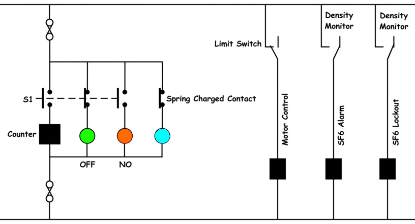
Operation Counter Function
One important auxiliary circuit is the operation counter. It is connected through a normally open (N.O.) contact of the breaker’s auxiliary switch. When the circuit breaker turns ON, this contact closes and increases the count by one. This helps us keep track of how many times the breaker has been closed.
ON OFF Indication in Circuit Breakers
Another helpful function is the ON/OFF indication using colored lamps. A normally closed (N.C.) contact stays closed when the breaker is OFF, which lights up a green lamp. When the breaker turns ON, another N.O. contact closes, lighting up a red lamp. These contacts are part of the auxiliary switch and are mechanically linked, meaning they move together based on the position of the breaker.
Spring Charging and Interlocking Mechanism
The spring charge indication is an important support function in the SF6 circuit breaker. A special limit switch is installed inside the spring charging motor. When the spring is not charged, the switch changes its position and sends power to a relay. This starts the charging process. Once the spring becomes fully charged, the switch returns to its original position. This stops the charging motor and turns on a blue lamp, showing that the spring is now fully charged and ready. Also, for safety, the circuit breaker is not allowed to close unless the spring is fully charged.
This is done by placing a contact (from the relay) in series with the closing coil. If the spring is not charged, or the spring is under charging process this contact stays open, and the breaker cannot be closed until the spring is fully charged.
SF6 Gas Density Monitoring System
The SF6 gas density monitor helps to maintain safety. It uses two pressure switches: one for giving an alarm and the other for creating a lockout condition. At first, when there is no SF6 gas inside the circuit breaker, the density monitor remains in a position that keeps its contacts open. When SF6 gas is filled to the required pressure, both density monitor pressure switches close. This energizes both the alarm coil and the lockout coil. As a result, the normally open (N.O.) contact of the lockout coil connected in series with the trip and close coils also closes.
This allows normal operation of the circuit breaker. At the same time, the normally closed (N.C.) contact of the alarm coil opens, preventing any alarm from sounding under normal pressure.
SF6 Gas Alarm
If the SF6 pressure begins to drop and reaches the alarm level, the pressure switch of the density monitor shifts its contact from closed to open. This de-energizes the alarm coil, causing its N.C. contact to close. If this contact is wired in the alarm circuit, an alarm will sound to alert the operator about the low SF6 gas pressure.
SF6 Gas Lockout
If the pressure continues to drop further and falls below the critical lockout level, the pressure switch of the lockout density monitor also opens. This de-energizes the lockout coil. As a result, its N.O. contact, connected in series with both the tripping and closing coils, also opens. This prevents any further tripping or closing operations. The breaker goes into a lockout condition for safety. This ensures the breaker does not operate under unsafe gas pressure, which could compromise insulation and arc-quenching ability during fault conditions.