Why do we use capacitor banks in the system?
Generally, these capacitor banks are connected in 33 kV systems. Normally, in a 33 kV system, we use a double star ungrounded capacitor bank. Before discussing the actual connection configuration of a double star ungrounded capacitor bank, let us recall the benefits of a capacitor bank in a power system network.
A capacitor bank mainly improves the power factor of the system. By improving the power factor of the system, it reduces the current loading of the system. That means it reduces the current loading for a specific quantity of power. By reducing the current load, a capacitor bank helps lower the I²R losses in the system.
As the current loading of the system is reduced, the transmission voltage drop decreases, thereby improving voltage regulation.
A capacitor bank also helps transmit more power from one point to another without exceeding the current-carrying capacity (ampacity) of the system. That means a capacitor bank introduces more power-carrying capacity to the system with the same current-carrying capacity.
Double star ungrounded capacitor banks are typically used in 36 kV systems, as they are the most common and effective configuration for medium-voltage power networks.
Double Star Ungrounded Capacitor Bank Connection
Let us take an example of a capacitor bank rated at 10 MVAR, 36 kV, 3-phase with 24 units. Each unit has 10.97 kV and 5552.46 kVAR. This capacitor bank has a double star ungrounded configuration. There are 24 capacitor units, so there will be 12 units for each star. This means the 24 units will be divided into two stars, and each star will have 12 capacitor units. Among the 12 capacitor units, 2 capacitor units are connected in series, and two such series are connected in parallel. So, each phase of each star gets 4 capacitor units. One capacitor unit has 14.61 microfarads, so two such capacitor units connected in series will result in 7.31 microfarads. Two such series combinations connected in parallel will result in four units giving a total of 14.61 microfarads again.
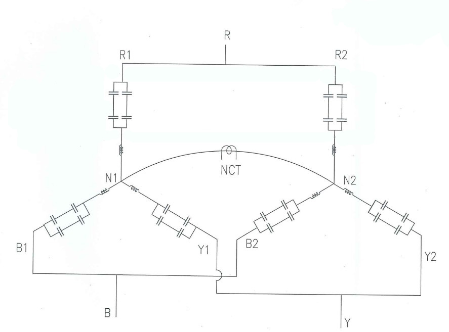
This double star configuration is very appropriate for internally fused capacitor units. Due to a short circuit or dielectric failure, if any capacitor element gets fused, that element will be eliminated from the internal circuit of the capacitor unit, and thereby the capacitance of the capacitor unit will be increased. The star points of the two stars are connected through a neutral CT. Under balanced conditions, there will be no current flowing through the NCT because the voltage at both star points is the same. If any capacitor element of any unit is fused, this balance will be disturbed. Therefore, an unbalanced current starts flowing through the neutral CT.
Protection of Double Star Ungrounded Capacitor Bank
Let us discuss the protection scheme of double star ungrounded capacitor bank. The value of unbalanced current flowing through the neutral CT during faulty conditions is given by the equation:
\[
I_u = \frac{3N \cdot N_2}{6N_2 \cdot N_1 – 6N \cdot N_1 + 5N} \times I_c
\]
Where,
\(I_u\) = unbalance current through the neutral (NCT),
\(I_c\) = current per capacitor unit,
\(N\) = number of failed capacitor units,
\(N_1\) = number of capacitor units in series per group,
\(N_2\) = number of groups in parallel.
This equation is derived according to IEEE standards. The unbalanced current in a capacitor bank is monitored and compared against predefined threshold values set for alarm and trip conditions.
Typically, there is a lower threshold (for example, between 50 mA and 100 mA) below which the unbalance is considered acceptable. Within this range, the capacitor bank can continue operating without significant impact, and only an alarm is triggered. This alarm indicates a possible minor issue such as the failure of some capacitor elements or tolerable degradation in capacitance.
However, if more capacitor elements fail, the unbalanced current increases. When it exceeds the upper threshold (300mA to 500mA), the protection relay issues a trip command to isolate the capacitor bank.
This protection is usually implemented using relays connected to the secondary of the neutral current transformer (NCT). Commonly used relays for this purpose include 51N (time-overcurrent), 59N (overvoltage neutral), and 87N (differential protection).
These relays can activate alarms when the unbalanced current crosses the alarming threshold and initiate tripping of a circuit breaker when the unbalanced current crosses the tripping threshold. The relays can also send data to the SCADA system.