A DC–DC converter is an electronic circuit. It changes one DC voltage level into another DC voltage level. It does this without changing DC to AC.
Why is a DC-DC converter needed?
Solar panels give variable DC voltages. Because the photovoltaic cells produce voltage depending on the intensity of sunlight. The load needs a fixed DC voltage. The load also has a fixed voltage. Thus, to feed power to the load, we need to maintain the feeding voltage. To keep the output voltage level, we need to maintain it even before converting the DC to AC. Therefore, we need a circuit to maintain the DC voltage level. A DC–DC converter serves this purpose.
A DC–DC converter chops DC voltage using a switch. It also stores energy temporarily. Additionally, it releases energy at a new voltage level.
Basic Components of a DC to DC Converter
It has the following basic components.
- DC source (Vin)
- Switch (S) – transistor or MOSFET
- Diode (D)
- Inductor (L)
- Capacitor (C)
- Load (R)
Buck Converter

We refer to this circuit as a Buck Converter. Because it reduces voltage. Here, in the diagram, we consider the output voltage across the load (Vout). To explain the working of the Buck Converter, we also denote the important nodes (voltage points)
- Output node (top of C and R) → Point C
- Between Vin and switch S → Point A
- Between switch S, diode D, and inductor L → Point B
Working of Buck DC–DC Converter
What happens when switch S is ON?
Let us consider the instant the Switch S closes. Then, Vin gets directly connected to the inductor. Hence, point A gets Vin. Point B obtains a slightly lower voltage than Vin. This is because of the drop across the switch (Transistor or MOSFET). Then the voltage at C appears after the drop across the inductor (L). Obviously, that shall be Vout. Now, the current flows from the source through the switch (S), then through the inductor (L), and finally to the Load (R).
Thus, the inductor (L) stores energy in its magnetic field. Additionally, the inductor current increases linearly. At the same time, the capacitor (C) charges. Diode (D) becomes reverse-biased (OFF). Point B is at a higher voltage (Vin). As a result, the cathode of the diode gets a positive voltage. At the same time, the anode or the diode is at ground potential. Hence, the diode blocks current.

Obviousely, here the inductor behavior is important. Here, the inductor voltage is\[V_L=V_{in}−V_{out}\]
Because of this voltage (VL), the load voltage Vout becomes reduced.
What happens when switch S is OFF?
Now, the switch S opens with the trigger signal. Hence, it disconnects Vin from the circuit. However, the inductor does NOT allow current to stop suddenly. To do so, the inductor reverses its polarity. So, at that instant, the voltage of point B becomes below zero potential. This forward biases the diode. At the same time, the potential of point C (Vout) remains the same due to the charged capacitor.

Now, the current flows from the Inductor (L) to the load (R). Then the current flows through the Diode (D) back to the Inductor. This is why we refer to this current as the freewheeling current. In this way, the inductor releases its stored energy. Simultaneously, the capacitor (C) supports the load to maintain its voltage Vout. In other words, it smooths the output voltage. It reduces the ripple. The inductor current decreases gradually to deliver energy to the load.
Role of Duty Cycle
We define the duty cycle as\[D=\frac{T_{ON}+T_{OFF}}{T_{ON}}\]Average output voltage is defined as,\[V_{out}=D\times V_{in}\]So, the increased duty cycle causes higher Vout. On the other hand, the decreased duty cycle causes lower Vout. D can not be greater than 1, because \(T_{ON}+T_{OFF} \geq T_{ON}\). Hence, the output voltage can not be greater than Vin. This is why this circuit is called a Buck Converter. We use it to reduce voltage.
Boost Converter
A boost converter is another type of DC–DC converter. Unlike a buck converter, it converts a low DC voltage into a higher DC voltage. In simple words, a boost converter steps up the input DC voltage.

A basic boost converter circuit has an inductor connected in series with the input source. Then we connect the switch between the inductor and the ground. We connect the diode between the inductor and the load. Lastly, we connect the capacitor across the load.
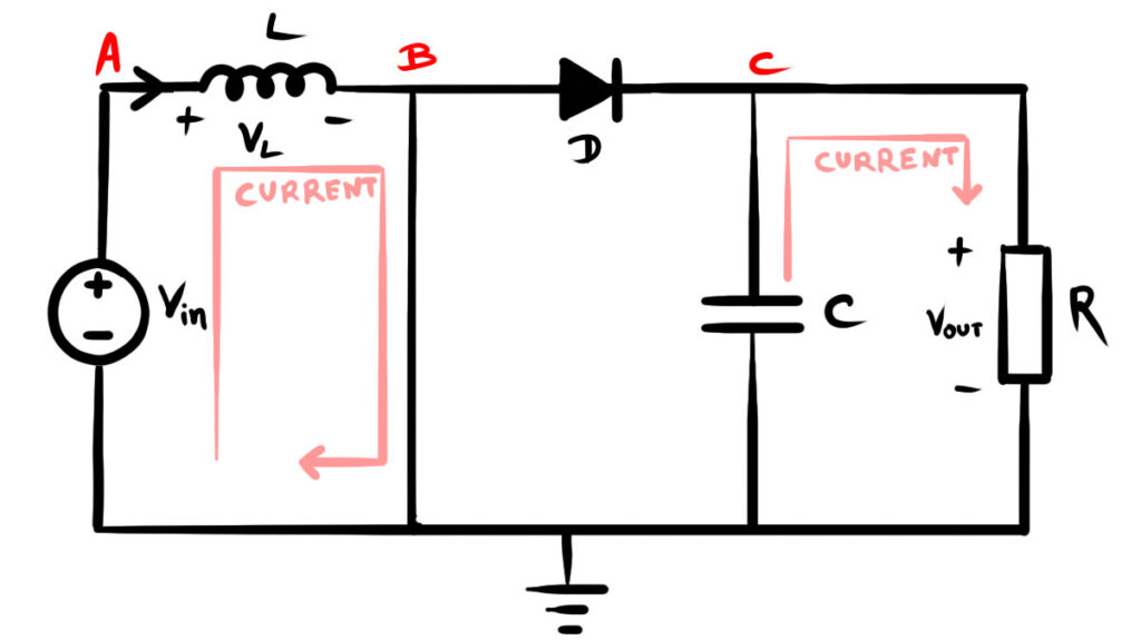
What happens when switch S is ON?
The trigger impulse at the gate terminal closes the switch (Transistor or MOSFET). The inductor is connected directly to the input source. Hence, the inductor current increases. Therefore, the inductor stores energy in it as magnetic energy. At this time, the diode becomes reverse-biased. Hence, the source becomes unable to supply current to the load. Thus, the capacitor only supplies power to the load. Also, the inductor voltage here equals the source voltage.\[V_L=V_{in}\]
What happens when switch S is OFF?
When the switch opens, the inductor resists the sudden change in current. The inductor reverses its polarity. Hence, the inductor voltage adds to the input voltage. Now, the diode becomes forward-biased. Hence, the energy gets a path to flow to the capacitor and load. So, the inductor voltage and input voltage add together. Then this added voltage appears across the load. This raises the output voltage. Hence, the capacitor also charges to a higher voltage.
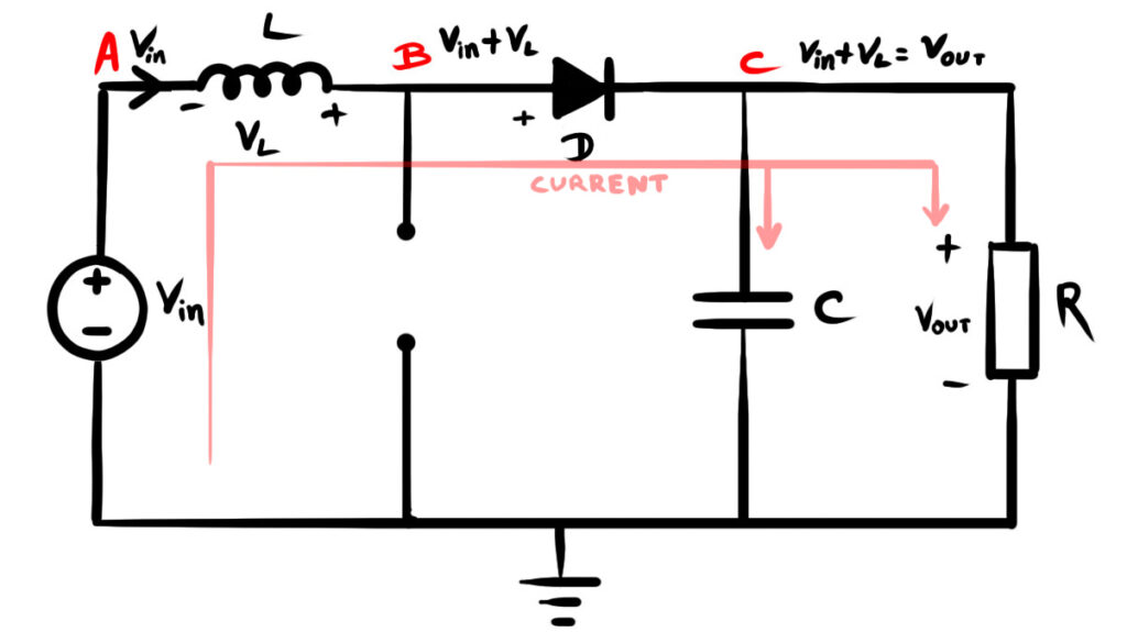
The output voltage of a boost converter becomes higher during the switch-off period. During this time, the inductor releases its stored energy, and its voltage adds to the input voltage. As a result, the combined voltage applied to the output side increases the output voltage level. The equation below gives the average output voltage of a boost converter
\[V_{out} = \frac{V_{in}}{1 – D}\]
Where ( D ) represents the duty cycle of the switching signal. As the duty cycle increases, the output voltage also increases.