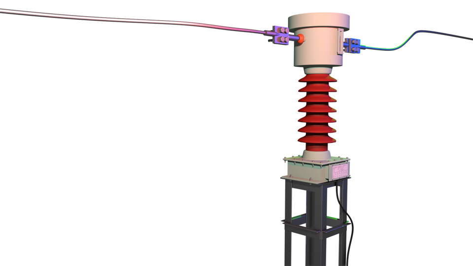
The current transformer is a kind of transformer that steps down currents. From the name “current transformer,” we can understand that it deals with current. The available instruments for measuring and protection purposes in the market are of a few amperes range. The ammeters, energy meters, wattmeters, and various protection relays are rated for only a few amperes.
Need for Stepping Down Current
A practical power system deals with many hundreds or even thousands of amperes. To measure such large currents or operate relays under high-current conditions, we need measuring and protection instruments rated for such high currents. However, manufacturing such instruments is not practical. Installing, handling, and transporting them is also difficult. In addition, they are not cost-effective. So, we need to go for smaller instruments that are rated for a few amperes. These are also readily available in the market.
Role of the Current Transformer
A current transformer (CT) makes a bridge between the actual network and the meters and relays used for measuring and protection purposes of the network. Its principle is very simple. A CT steps down the actual current flowing through the power circuit. It reflects the variation of actual network current at the instrument end, but in much smaller magnitudes. It means the variation of network current will have a replica on the instrument side, but in a measurable and tolerable magnitude.

Theory of Current Transformer
From a construction point of view, a current transformer is very simple. It is somewhat similar to a power transformer. The main difference is that a current transformer has one or a few turns in its primary winding, and the secondary winding contains a much higher number of turns. The number of secondary turns depends on the ratio at which the current is stepped down. Like a general power transformer, a current transformer has magnetic cores. These cores magnetically link both the primary and secondary windings.
Example and Formula
Suppose we need to have one ampere at the instrument end when the primary current through the network line is 1000 amperes. As we know from the basic principle of transformers, the number of turns multiplied by the current in the winding is the same for both primary and secondary windings. So, if we keep one turn in the primary and 1000 turns in the secondary, then we get this equation, \[1000 \times 1 = 1 \times 1000 \text{ or } N_1 \times I_1 = N_2 \times I_2 \] Where \(N_1\) is the number of turns in the primary winding, and \(N_2\) is the number of turns in the
secondary winding. \(I_1\) is the primary current, \(I_2\) is the secondary current.
So, for a current transformer, we can finally write \[\frac{I_1}{I_2} = \frac{N_2}{N_1} \]

