
Wound Type CT
The Wound type CT uses a magnetic core. The core of the CT consists of laminations of cold-rolled, grain-oriented silicon steel. Some manufacturers also use nano-crystalline core material for this purpose. This creates a closed magnetic path.
We wrap insulating paper around this closed magnetic path (core). Over the paper insulation, we wrap enameled copper wire to form the secondary winding of the CT. Next, we wrap the thicker, insulated primary conductor for two or three turns. We then connect the primary winding to the primary terminals and the secondary winding to the secondary terminals.
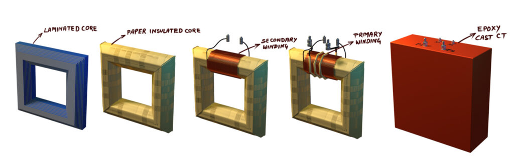
After that, we mold the entire assembly with epoxy resin to form a solid CT structure. The primary conductor is wound on the core, so we call it a wound-type current transformer.
A wound-type current transformer provides higher accuracy than a bar-type CT. Because the primary winding has more than one turns, we can reduce the number of turns in the secondary winding. Therefore, this design offers better accuracy than a simple bar-type or through-type CT.
Toroidal or Window Type CT
A toroidal or window-type current transformer uses a ring-shaped ferromagnetic core. Manufacturers form the core by rolling cold-rolled, grain-oriented silicon-steel strips. They shape these strips into a ring. They apply insulation on the lamination surface. This insulation prevents eddy currents in the core. The grain orientation of the silicon steel reduces hysteresis loss.
Then they wrap insulating craft paper around the ring. Obviously, this layer provides insulation. Then we wrap enamel-coated copper wire on the ring. This winding forms the secondary of the CT. Next, they bring out the terminals of the secondary winding. Finally, they mold the entire assembly with epoxy or resin. This molding forms the ring-shaped CT body.
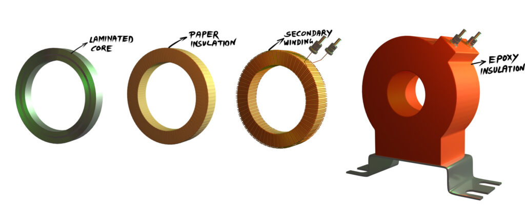
The CT has an opening or “window” at its center. The primary line conductor passes through this window. This conductor works as the primary winding. Therefore, the CT does not have a separate primary winding. Its construction includes only the core and the secondary winding. These parts remain enclosed within the resin-cast insulation. The secondary terminals come out from this molded structure.
This CT offers several advantages. It is inexpensive. It is easy to install. Its construction is simple. However, it does not provide very high accuracy. The central conductor may not pass exactly through the center of the window. This off-center position causes uneven flux distribution in the core. The uneven flux creates measurement errors.
Bar-Type Current Transformer (Bar CT)
In a bar-type CT, a solid aluminum or copper bar passes straight through the CT window. Manufacturers insulate this bar according to the voltage level of the CT. The bar works as the primary winding. We have to select its cross-section carefully so it can carry the full rated line current without overheating.
We wind the secondary winding on the CT core. Manufacturers use laminated strips made from cold-rolled grain-oriented (CRGO) silicon steel or nanocrystalline material to form the core. They place paper or plastic insulation over the core. After that, they wrap the secondary winding on the ring-type core. Then, epoxy or resin cast together the secondary terminals, core, secondary winding and the insulated bar section.
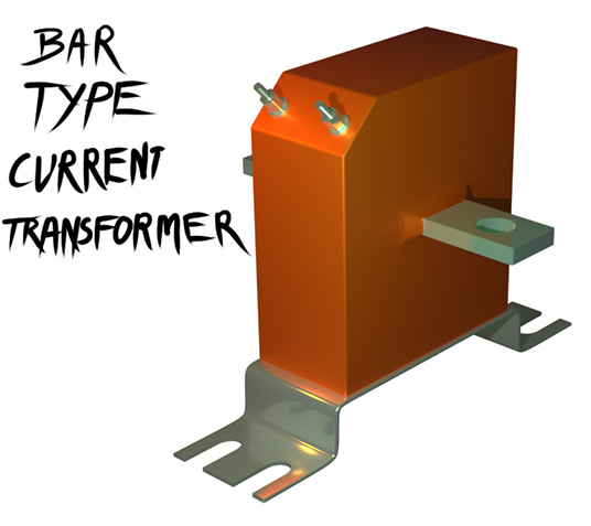
This casting creates a strong, stable, and rigid structure. Bar CTs can handle very high currents and strong mechanical forces during faults.
You should remember that we normally use solid epoxy-cast or resin-cast CTs only up to 33 kV. At higher voltages, the insulation thickness becomes too large. This makes the CT very heavy, bulky, and mechanically unstable. Therefore, engineers limit bar-type and other solid-core CT constructions to 33 kV systems.
We usually install these CTs in indoor switchgear of 11 kV and 33 kV. Because of their strong construction, bar CTs can handle very large fault currents.
Bushing Current Transformer (Bushing CT)
A bushing CT is a ring-type CT where the manufacturer winds the secondary on a core and brings the terminals out. They insulate the entire assembly with paper and place it inside the turret of a power transformer.
This is why we call it a bushing CT.
Every high-voltage, medium-voltage, and low-voltage bushing may contain CTs for essential measurements.
These CTs help in measuring winding temperature indication, restricted earth-fault protection, and differential protection of the transformer.
Split-Core Current Transformer
A split-core CT is basically a ring-type CT with a core that opens to allow a conductor to pass through. We normally use split-core CTs in portable measurement instruments such as tongue testers (clamp meters). However, a split core creates an air gap. This air gap reduces accuracy because the flux distribution in the core may become non-uniform if the meter is not properly hold.
Oil Immersed Outdoor CT
So far, we have discussed all the indoor types of current transformers. Now we will focus on the outdoor types. We install outdoor CTs in 33 kV and above switchgear systems. In these voltage levels, using solid-cast insulation is not economical. As mentioned earlier, solid epoxy or resin-cast CTs become bulky, heavy, and mechanically unstable because the required insulation thickness is very high.
Engineers solved this problem by introducing oil-immersed outdoor CTs. These CTs come in two types
Dead-Tank Current Transformer
In a dead-tank CT, the primary conductor comes down inside the tank. The tank is directly connected to the ground grid of the substation. So, the tank always remains at earth potential.
Manufacturers make the core using laminated cold-rolled grain-oriented (CRGO) silicon steel or nanocrystalline material. The core has a ring shape. The primary conductor passes through this ring as either a single turn or a few turns. The core carries the secondary winding. Engineers provide proper insulation, between the primary and the core and between the core and the secondary winding. The level of insulation depends on the voltage class. An insulation housing is placed between the line terminal and the grounded tank. Then we fill entire CT with insulating oil, which improves dielectric strength and cooling.
Live-Tank Current Transformer
Another outdoor type is the live-tank CT. This CT works similarly as a bar-type CT, but here the insulation method is different. The primary conductor is a solid aluminum or copper rod. Then this rod passes through the ring-type core. The secondary terminals from the core run down to the bottom of the CT. Here, an insulating housing supports the CT . The core, secondary winding, and primary bar are all paper-insulated. Then, they are enclosed in a metal tank made of aluminum, or steel.
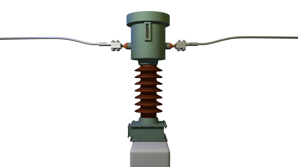
One end of the primary rod is insulated from the metal cover. The other end is directly connected to the tank body. Because of this, the tank remains at line (live) potential. This is why we call it a live-tank CT.
The weight of the CT remains in the upper portion. This makes the live-tank CT slightly less mechanically stable than the dead-tank CT. However, for very high-voltage applications, such as 220 kV and above, the live-tank CT is generally the only economical option. It is more cost-effective to manufacture live-tank CTs than a dead tank CT for ultra-high-voltage systems.
Functional Classification of CTs
We can also classify CTs based on their application. A current transformer serves two purposes:
- Metering
- Protection
The core design for metering CTs is not the same as the design for protection CTs. Metering CTs require high accuracy at normal operating currents. Protection CTs must remain unsaturated during fault currents, which are much higher. So, depending on the core design, we classify CTs into:
- Metering CTs – used in measuring instruments and energy meters
- Protection CTs – used in protective relays and fault detection