
A high-voltage power system deals with a huge quantity of currents. Unfortunately, the huge size of meters or protection relays is not available in the market. For cost and size optimization, the meters and relays are normally designed with a 1 A or 5 A rating. Therefore, there must be some means by which we can step down this huge current to a manageable value.
Purpose of a Current Transformer
A current transformer performs that task. It reproduces a replica of the power line current to much smaller and manageable amplitude.
Obviously, a current transformer is a kind of instrument transformer. The current transformer steps down the power line current. It reduces the current to a manageable value for measurement, metering, and protection devices. It also ensures the electrical isolation of the relay and metering circuits from the main power network.
Working of a Current Transformer
A current transformer operates on the same principle as a conventional power transformer. However, there is a small difference from a power transformer.
In a power transformer, when we connect a load to the secondary, the primary draws the required current from the source. This current fulfills the load demand at the secondary.
On the other hand, a current transformer does not have any control over the primary current. This is because we connect the current transformer directly in series with the line. So whenever current flows through the line, it also flows through the primary of the CT. The load (burden) connected to the secondary of the CT does not have any control over the primary current.
In that respect, the working principle of a current transformer differs from the working principle of a power transformer.
Turns Ratio and Current Ratio
A current transformer typically has very few turns in the primary winding. Sometimes it may have only one turn. Even sometimes, the primary goes straight through the center of the core of the CT. However, the flux produced in the core of the CT is not negligible. This is because the ampere-turns are very large due to the huge current in the primary circuit.
Now suppose there are Ns number of turns in the secondary coil of the current transformer. Obviously, \[ N_p \times I_p = N_s \times I_s \]This is because the flux generated by the primary current (Ip) links with the secondary coil. Again, the number of turns (Ns) in secondary is large. Therefore, to balance the flux generated by the primary current (Ip), the secondary current (Is) will be reduced accordingly.
If there is only one turn in the primary side (Np = 1), we can write \[1 \times I_p = N_s \times I_s\] \[\text{Therefore, } N_s =\frac{I_p}{I_s}\]
If we know the nominal current rating of the power circuit, then for a 1 A CT we can easily calculate the number of turns required in the secondary winding.
Also, by using the same formula, we can easily calculate the number of turns in the secondary winding for a 5 A.
\[\text{Here , } I_p =N_s\times 5\]\[\text{Therefore, } N_s =\frac{I_p}{5}\]Hence, in 5 A CT, the number of turns in the secondary winding is five times less than that in a 1 A CT.
Comparisons between 1 A and 5 A CTs
Because, due to fewer turns in the secondary, the size of the 5 A CT becomes smaller than that of the 1 A CT. This is one advantage of a 5 A CT over a 1 A CT.
However, there is a disadvantage, also. Due to the higher secondary current of a 5 A CT, more voltage drop occurs in the secondary circuit than that in a 1 A CT. Because of that, if the distance between the CT and the relay or meter is long, engineers always recommend using a 1 A CT instead of a 5 A CT.
However, where space is the main constraint, engineers prefer to use a 5 A CT. Although, in that case the engineers try to reduce the distance between the relay/meter and the CT as much as possible. For example, 5 A CTs are most suitable in indoor switchgear. Because here, the relays, meters and CTs are installed in the same cabinet.
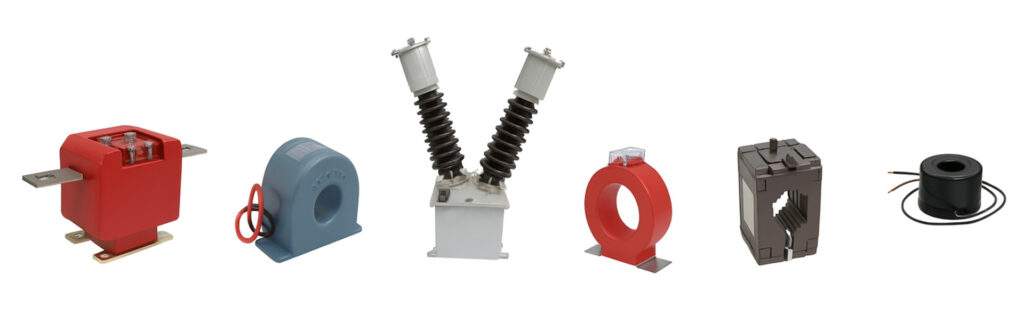
Basic Construction of a CT
A current transformer has three main parts. The primary winding consists of very few turns or a single bar. Obviously, there will be a magnetic core facilitate proper flux linkage between the windings. To reduce eddy-current and hysteresis loss, high-grade cold-rolled grain-oriented silicon steel laminations are used for the core. The secondary winding of a current transformer consists of a significant number of turns depending upon the current rating. The secondary winding feeds the meter and relay. Normally, manufacturers use copper wires to construct the secondary windings.
An oil-filled container, resin-cast, or epoxy-cast is used to cover the entire current transformer to provide insulation.