Normally, most of the utilities use double star ungrounded neutral capacitor banks. They connect series and parallel capacitor units to form that double star design. They normally use it in 33KV systems of electrical power substations.
Before going to the detail protection scheme of double star ungrounded 3-phase capacitor bank, we may recall the connection configuration of a double star ungrounded capacitor bank.
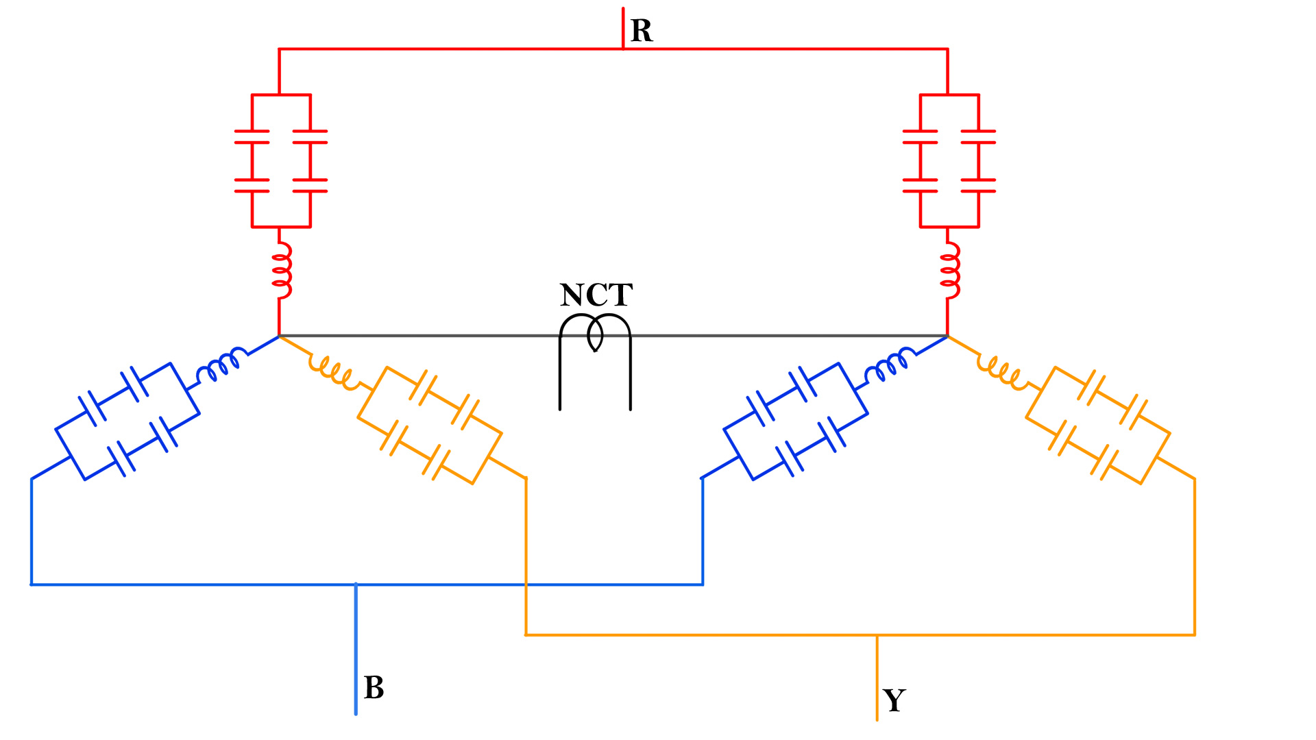
Connection Diagram of Double Star Ungrounded Capacitor Bank
In a double star ungrounded capacitor bank, the group of each phase of each star is typically formed by connecting a specific number (two or more) capacitor units in series, and then a specific number (two or more) of such series capacitor units in parallel. By assembling three such identical groups, one star of the capacitor bank is formed. Now there is another similar star connection using the same identical configuration of same identical capacitor units. Now star-point of these two stars are connected via a neutral CT.
Unbalance Protection of a Capacitor Bank
If any element of a capacitor unit in any phase of a star is fused, the effective capacitance of that phase of the star will decrease slightly, depending on the value of the fused element. As a result, the total reactance across that phase will increase accordingly because the capacitance of the failed element has been removed from the circuit. As a result, the overall voltage of that phase of that star will be increased. Because of this increased voltage, the voltage balance between two star-points, will be disturbed.
That means a potential difference is created between the star-point of first star and the star-point of the second star. Hence, there will be an unbalanced current flowing through the neutral CT. Thereby, the unbalance relay associated to that neutral CT will initiate either an alarm or a trip signal.
However, it is important to note that if a single capacitor element in any unit gets fused, there will be a slight increase in voltage across the string where that element was connected. This minor voltage rise should not trigger the capacitor protection scheme, as the small reduction in capacitance does not significantly impact the overall performance of the capacitor bank. Therefore, the protection system should not initiate a trip signal.
Therefore, a threshold voltage level should be defined, only beyond which the trip signal can be initiated, and below which only an alarm is generated. As a general rule, the unbalanced relay triggers an alarm if the overvoltage due to one or more capacitor element failures remains within 10% of the rated voltage. If multiple capacitor elements fail and the resulting voltage rise exceeds 10% of the nominal voltage, then the relay should generate a trip signal. It will isolate the capacitor bank instantaneously from the system.
This is the typical protection scheme used for ungrounded double star capacitor 3-phase capacitor bank.
Overvoltage and Undervoltage Protection
The second protection scheme is used for the capacitor bank: overvoltage and undervoltage protection.
The overvoltage and undervoltage relays associated with that capacitor bank are fed from the bus PTs. If the voltage of the capacitor bank crosses the upper threshold limit, the overvoltage protection will be actuated and the capacitor bank will be isolated from the system by operating the circuit breaker.
In the same way, if the voltage dips or reduces below the predetermined threshold value the undervoltage relay will be actuated to trip the capacitor bank from the rest of the system. Although there is a specific time delay provided to the both over voltage and under voltage relays to prevent the capacitor bank against mal tripping for any transient voltage fluctuation.
Overcurrent and Earth fault Protection
Also, in capacitor bank bay, normal line-side current transformers feed the overcurrent earth-fault relay associated with the capacitor bank. In normal the normal events of overcurrent and earth faults, this relay will trip the circuit breaker to isolate the capacitor bank from the rest of the system.
These are the main three types of protections used in 33 kV capacitor banks.
- Unbalanced current protection through neutral CT connected across the star-points of the double star 3-phase capacitor bank.
- Undervoltage and overvoltage protections where the voltage is fed to the undervoltage and overvoltage relays from the bus PT of 33 kV system.
- General overcurrent and earth-fault protection which is fed from the CTs of the bay of the capacitor bank.