In this specification, we shall discuss the design, assembly, and testing details of Indoor Switchgears with Vacuum Circuit Breaker.
Most commonly, we apply these switchgears for 11 KV systems and sometimes for 33KV systems. The manufacturers generally manufacture modern indoor switchgears for 1250A to 800A normal current rating with 25 KA as its short circuit current withstand capability for 3 seconds. The vacuum circuit breaker used in the gear uses the shunt trip mechanism. The circuit breakers also spring-spring mechanism for both closing and opening the CB. The circuit breaker comprises the motor-operated spring charging mechanism. Also, the indoor switchgears with a vacuum circuit breaker are compatible with SCADA.
If we go for an 11 kV system, the rated voltage of the system is 12KV. The other parameters for the system are listed below,
| Power Frequency withstand Voltage (1min) | 28 KV rms |
| Lightning Impulse withstand Voltage (1.2 / 50 micro-sec) | 75 kVp |
| Rated Breaking Current | 800A / 1250 /1600A |
| Rated Symmetrical Short Circuit Current for 3 sec | 25 KA rms |
| Rated Asymmetrical Short Circuit Current for 3 sec | 1.55 X 25 KA rms |
| Rated Dynamic Peak withstand Current | 2.5 X 25 KA peak |
| Control DC Voltage | 30/110/220 V |
Construction of Indoor Switchgears
The main configuration of an Indoor Switchgears comprises a single three-phase bus. The bus is not a continuous one. It has a bus section gear in the mid portion. Two incomer switchgears are connected to the two sections of the bus. The switchgears for the outgoing feeders are connected to these two parts of the bus.
Each switchgear panel is a stationary type. Each of the switchgears is enclosed in a self-supporting sheet-steel cubicle. The circuit breaker in each cubicle is of the vertically isolating, horizontally draw-out type. Another main feature of indoor switchgears with VCB is that all the circuit breaker assemblies are available irrespective of their normal current ratings. It permits complete interchangeability of the circuit breaker unit among all cubicles in the indoor switchgear board. In other words, the incoming, outgoing, and bus-coupler breakers are all identical so that we can use any of them in any panel. This maximizes the maintenance flexibility. The cubicle is generally made with a minimum 2 mm thick steel sheet.
Construction of Cubicles
There must be a front access door in each cubicle. It must also have a removable back cover. The circuit breaker, bus-bar, instrument transformer, and cable end box shall be installed in separate compartments within the cubicles.
Suitable vent shall be provided for satisfactory performance. Each compartment shall be separated from the adjacent one by a sheet steel barrier.
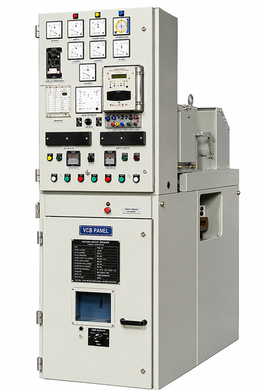
The hinged front door of the upper cabinet of the indoor switchgear cubicle contains relays, meters, switches, and lamps. We refer to this part of the switchgear as the control cabinet of the cubicle.
Terminal Blocks
The terminal block is provided inside the control cabinet of the cubicle. All the secondary leads from the current transformers and potential transformers terminate at terminal blocks. Preferably, these terminal blocks are of the disconnecting type in the CT PT Circuit. Preferably, a transparent cover is used on the block. There should be a test terminal block of the metering circuit. There must be some spare terminals for customized use at the customer end. We prefer to provide at least 25% spare terminals for this purpose.
Bus and Bus Taps
The main bus of each section is of high-conductivity electrolytic copper. Normally, we use a 1600A-rated bus bar. The bus-bar shall be provided with insulating sleeves, and joints shall be provided with insulated, removable shrouds. All bus connections, joints, and taps shall be tinned or silver-plated. The bus and other conductor connections shall be as short and straight as possible.
Control AC and DC Supply
We need to provide DC and AC control power to only the incoming and bus coupler panel. Then we need to run bus wires to distribute these power supplies to the different cubicles of the multi-panel board. The manufacturer shall provide isolating fuse units for the incoming AC and DC control power supplies to each switchgear unit.
Wirings
The manufacturers should provide all wiring for the protection, metering, indicating, etc., within the cabinet. Also, they need to uses shall be provide proper removable fuse grips to disconnect individual circuits from bus wires without disturbing the other circuits. All wiring shall be done with flexible PVC-insulated standard copper wires. For limiting the burden of metering and relaying circuits, we use 4 sq.mm copper wires for the current transformer secondary. Although, as the distance from CT to relays and meters is quite small in an indoor switchgear panel, we may use 2.5 sq mm copper wires instead. Although it is good practice to use 4 sq mm wires for this purpose. However, we prefer 2.5 sq mm copper wires for voltage circuits, control circuits, alarm circuits, and signalling circuits. However, manufacturers must use 4 sq mm for the main AC and DC bus wires.
One important thing to note here is that there must not be any other fuse other than the main PT secondary fuse in the potential metering circuit.
Circuit Breaker Closing Mechanism
The manufacturers must provide a handle for manual spring charging along with the motor-operated spring charging mechanism. The closing circuit must be equipped with an anti-pumping relay. The closing mechanism must be trip-free in nature.
HT Cable Terminations
The manufacturers preferably provide a double cable termination arrangement at the rear side of the incomer gear panel. This is for the forecasted future enhancement of demand. For the outgoing feeder panel, only a single power cable termination is enough. HT Power Cable for connection to shunt capacitor bank or connection to another multi-panel switchgear shall enter the multi-panel board equipment from the side of the panel through the right-angle side entry cable end box.
HT Power Cables
We use 11 kV, 3-core XLPE aluminium power cables from the switchgear terminations. The standard size of the cable used in an 11 kV system is normally 300 sq. mm cross – section.
Ground Bus
A grounding bus rated to carry maximum fault current shall be furnished along the full length of the panel board. Each stationary unit shall be grounded directly to the ground bus.
Vacuum Circuit Breaker Truck
Generally, the circuit breakers are of the draw-out type. Each circuit breaker is equipped with mechanical close and open facilities. Also, it must have mechanical ON and OFF indicators. Trip circuit, healthy indication and spring charging indication are to be provided on the front of the panel.
Each breaker assembly shall have the markings of SERVICE, ISOLATED, and WITHDRAWAL positions marked. Each breaker shall also have mechanical indicators for spring CHARGED and DISCHARGED conditions. There must be a mechanical safety interlock that prevents putting the CB truck into the cubicle unless the truck is secured in position.
There will also be a mechanical interlocking system that blocks the lowering of the truck unless it is properly opened. One can only withdraw or insert the truck in the cubicle when it is at the withdrawable position. Also, one can only operate the CB at the service position unless its male-female isolating contacts are fully engaged. The safety shutters completely cover the female primary contacts when the CB truck is disconnected or withdrawn.
Busbar and feeder spout shutter screen be padlocked independently. The circuit breaker racking equipment can be padlocked in any position.
We can also electrically open or close the VCB using a trip–neutral–close (TNC) control switch. spring-controlled switch with. Electrical close and trip operation should be dependent on the Local/Remote Switch. However, the protection trip and emergency trip circuit should be independent of the Local/Remote Switch. Each breaker truck must have an operation counter.