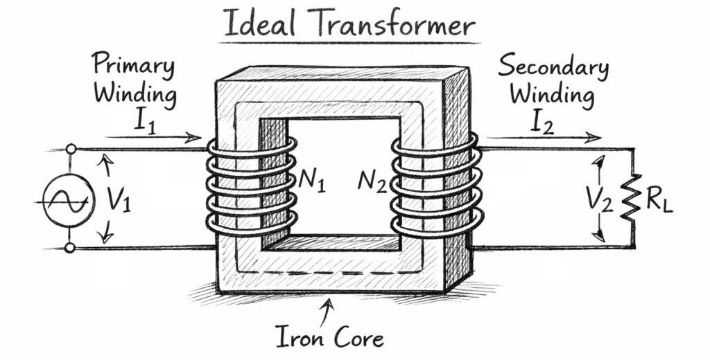
Here, we will discuss the ideal transformer. First, let us understand what an ideal transformer is.
An ideal transformer is a transformer that has no losses. The word “ideal” means the transformer operates with 100% efficiency. A transformer becomes 100% efficient only when there is no power loss.
Why does power loss occur in a transformer?
Power loss occurs in a transformer mainly due to two reasons. The first is copper loss, also known as ohmic loss. The practical transformer windings have their own resistance. Because of this resistance, loss occurs in the winding in the form of I²R loss.
No Copper Loss in an Ideal Transformer
In such an imaginary transformer, there will be no resistance in the windings, so there will be no copper loss.
No Core Loss in an Ideal Transformer
The second is core loss, also we call it as iron loss. Core loss includes hysteresis loss and eddy current loss. In an ideal transformer, the core will be completely free from both hysteresis loss and eddy current loss. Therefore, there will be no core loss.
No Leakage Flux
In an ideal transformer, there will also be no leakage flux. Hence, there will be no leakage reactance in the windings. This means whatever flux the primary produces, the entire flux will link with the secondary. As a result, there will be no leakage flux.
Perfect Voltage Regulation
Because there is no resistance and no leakage reactance, the voltage regulation will always be perfect. This means the voltage that appears across the load will be exactly equal to the voltage induced across the secondary winding. Since there is no resistance and no reactance to cause any voltage drop in the winding.
No Load Current in an Ideal Transformer
In an ideal transformer, the transformer will draw only the magnetizing current, with no core loss component. Because the core of such an imaginary transformer is loss-free. Magnetizing current magnetizes the core and produces the magnetic flux. This flux links with both the primary and the secondary windings. Due to this changing flux, the emf is induced across the primary and secondary windings.
Phase Relation between Primary and Secondary EMF
Also, the induced emf across the primary will be 180o opposite to the applied primary voltage. This happens because the induced EMF is the effect of the applied primary voltage. For the same reason secondary induced emf will also be in opposition of primary supply voltage.
In reality, an ideal transformer does not exist. However, we still study such an imaginary transformer concept because it helps us analyze a practical transformer.
Short Video on Ideal Transformer