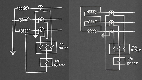
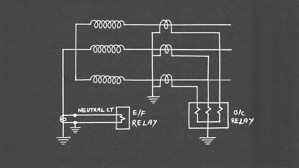
A simple overcurrent (O/C) and earth fault (E/F) protection is essential for a power transformer. The O/C protection operates whenever the phase current exceeds a preset value. E/F protection responds to residual or zero-sequence current. Overcurrent and earth fault protection of power transformers uses simple IDMT or DMT relays. It cannot distinguish between internal and external faults of the transformer. Hence, it operates for both.
Although it is not the primary protection of a power transformer, it acts as backup protection. Due to this, we use simple IDMT or DMT relays for the purpose. These relays provide a time-delayed operation. The time delay ensures that the relays only operate once the primary protection of the transformer fails.
IDMT and DMT Relays
IDMT implies Inverse Definite Minimum Time. The operating time of the relay decreases as fault current increases. Although, there is a definite minimum time beyond which the relay cannot operate. On the other side, a DMT relay operates only after a preset minimum time delay, even for extremely high currents. Hence, both relays allow engineers to provide the required time grading to maintain proper coordination of operation with other protection schemes.
Why O/C and E/F Protection is Called Backup Protection?
The O/C and E/F protection is a kind of backup protection. Firstly, it does not discriminate between internal and external faults. Secondly, it responds to through-fault currents irrespective of fault location. Transformer differential protection and restricted earth fault protection operate faster and more selectively. These two protections come under the primary protection scheme of transformers. Once any of the primary protections trip the circuit breakers, the O/C and E/F relays automatically deactivate by returning to their initial normal position. The O/C and E/F relays can only complete their operation if primary protections fail to isolate the fault in time.
Location of O/C and E/F Protection (HV or LV Side)
The same fault produces a lower current on the HV side. We commonly use O/C E/F backup protection for small power transformers (<10 MVA) on the HV side. Therefore, one set of CTs protects the transformer along with the downstream LV network. Obviously, it simplifies the protection scheme. Additionally, it reduces installation costs. Although the operation of O/C or E/F relays on the HV side sends trip signals to open breakers on both sides. This is called inter-tripping.
Bigger transformers (>10MVA) demand backup protections on both HV and LV sides. This is because if the LV backup protection fails during an LV fault, the HV backup clears it. Conversely, during the failure of HV backup protection, LV backup can clear the HV faults. Also, during the failure of the unit protection, the internal transformer fault can be seen from both sides. Additionally, the failure of the circuit breaker on either side of the transformer demands that the other side provide backup.
- Smaller transformers (<10 MVA) may have simplified backup only on the HV side.
- Bigger transmission transformers (>10 MVA) always have a comprehensive backup on both sides.
Directional Backup Protection of Transformer
Grid-connected parallel transformers demand direction elements in their backup relays. Because here, power can flow in either direction (reversible substations). In such cases, directional overcurrent relays (67) ensure backup protection operates only for faults in the intended direction.
Relay Coordinations
The transformer backup protection must be time-coordinated with the primary unit protections, downstream/upstream protective devices, and the protections on the opposite side of the transformer.
LV feeder protection actuates almost instantaneously (within 0.3s). This is because, due to a feeder fault, the feeder must trip alone. For that, we set the LV transformer backup to 0.4s to 0.6s. This delay prevents the transformer from tripping for a feeder fault. Because any downstream feeder fault also initiates a through fault condition in the transformer. Similarly, to avoid unnecessary tripping of upstream incomer feeders due to any fault in the transformer, we set a longer delay time for the HV upstream backup.
To understand the working of Transformer Backup Protection, you may watch the following video