In this article, we are going to discuss the theory behind a condenser bushing. We have mainly focused on how the capacitor grading improves the voltage distribution along the thickness of the insulation. We also call it a capacitor graded bushing. There are mainly two types of condenser bushings. These are the OIP bushing and RIP bushing. The OIP bushing stands for oil-impregnated paper bushing; on the other hand, RIP stands for resin-impregnated paper. Obviously, both of these types of bushing are superior to the resin-bonded paper bushing, or RBP bushing, or SRBP bushing.
What is a Bushing?
A bushing is a part of an electrical apparatus that provides electrical insulation between the live and earthed portions of the equipment. In other words, it acts as an insulating barrier between the live conductor and the grounded metal enclosure of the equipment.
There are several types of bushings we use in high-voltage systems. For voltage levels up to 33 kV to 72.5 kV, utilities often use RBP bushings or SRBP bushings because they are economical and easily available.
However, when the system voltage exceeds 72.5 kV (such as 132 kV, 220 kV, 400 kV, or higher), RBP bushings perform poorly. In such cases, capacitor graded transformer bushings, which include both OIP and RIP types, ensure uniform voltage distribution.
Limitations of Resin Bonded Paper (RBP) Bushings
Normally, an RBP bushing does not have any capacitor grading arrangement. In other words the voltage distribution across the insulation is not uniform. The electric field (or potential gradient) is highest near the conductor and decreases exponentially toward the earthed flange, rather than decreasing linearly.
Limitations of Non-Graded Bushings
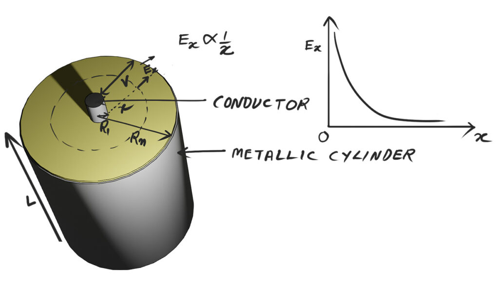
Suppose around a conductor, there is a metallic cylinder. In addition, there is a uniform gap between them. The radius of the conductor and the outer metallic cylinder are \(R_1\) and \(R_N\), respectively. There is a dielectric medium in the space between them. Here, we may use either oil-impregnated paper or resin-impregnated paper as the dielectric. When we apply a voltage V between these two conductors, it establishes an electric field in the dielectric medium. Additionally, let Q be the total charge on the inner conductor.
Let us consider a point at a distance x from the center of the conductor. Suppose the electric field intensity at that point is \(E_x\). For a cylindrical surface of radius x and length L, the surface area is: \[A = 2 \pi x L\]
According to Gauss’s Law, the total electric flux through this surface equals to the charge enclosed divided by the permittivity of the medium \(\varepsilon\) i.e. \[E_x 2 \pi x L= \frac{Q}{\varepsilon}\] From this, we can express the electric field as: \[E_x = \frac{Q}{2 \pi L \varepsilon x} \text{(Equation 1)}\]
Voltage Between Inner and Outer Cylinders
To obtain the total voltage between \(R_1\) and \(R_N\), obviously we have to integrate the electric field along the radial distance.\[V = \int_{R_1}^{R_N} E_x \, dx\]Substituting the expression of \( E_x \) from the previous expression: \[V = \int_{R_1}^{R_N} \frac{Q}{2\pi L \varepsilon x} \, dx\]\[= \frac{Q}{2\pi L \varepsilon} \int_{R_1}^{R_N} \frac{dx}{x}\]\[= \frac{Q}{2\pi L \varepsilon} \ln\left(\frac{R_N}{R_1}\right) \text{(Equation 2)}\]
Relationship Between Field and Voltage
Now, from Equations (1) and (2), we get,
\[E_x = \frac{Q}{2\pi L \varepsilon x}\]
\[V = \frac{Q}{2\pi L \varepsilon} \ln\left(\frac{R_N}{R_1}\right)\]
Eliminating Q from these two equations, we get
\[E_x = \frac{V}{x \ln\left(\frac{R_N}{R_1}\right)}\]
Nature of the Electric Field Distribution
From the above expression of \(E_x\), we can see that \(E_x\) is inversely proportional to the distance x: \[E_x \propto \frac{1}{x}\]. This means:
- Near the conductor (where x is small), the electric field intensity is very high.
- As we move outward (increasing x), the field strength decreases rapidly.
Hence, the curve between \(E_x\) and x is hyperbolic in nature. It starts high near the conductor and falls gradually toward the outer surface.
Problem of Uneven Voltage Distribution
This non-uniform field distribution leads to a concentration of dielectric stress near the central conductor. As a result, the insulation experiences maximum electrical stress near the conductor. Therefore, this may cause partial discharges.
Concept of Condenser Bushing or Capacitor Graded Bushing
We design a condenser bushing to distribute the voltage uniformly across the insulation using capacitor grading. In this design, we insert concentric layers of aluminum foil between layers of insulating kraft paper around the central conductor. Each pair of foil layers with impregnated paper in between forms a cylindrical capacitor. Obviously, all such capacitors are in series. Consider one of such cylindrical capacitors. Say this is \(i^{th}\) capacitor from the center.
Let the:
- Radius of the inner metallic layer = \(R_i\)
- Radius of the outer metallic layer = \(R_{i+1}\)
- Potential difference between these two layers = \(V_i\)
Then the voltage developed between two successive aluminum layers can be expressed as:\[V_i = \frac{Q}{2\pi \varepsilon L} \ln{\left( \frac{R_{i+1}}{R_i} \right)}\]
Condition for Uniform Voltage Distribution
To achieve equal voltage across each layer (that is, \(V_1 = V_2 = V_3 = \cdots = V_i = \cdots =V_N\)), the ratio of successive radii must be constant. That is: \[\frac{R_2}{R_1} = \frac{R_3}{R_2} = \frac{R_4}{R_3} = \cdots = \frac{R_{i+1}}{R_i} = \cdots = \text{constant}\] Maintaining this constant ratio ensures that each capacitor formed by two adjacent foils has the same capacitance, given by: \[C_i = \frac{2\pi \varepsilon L}{\ln{\left( \frac{R_{i+1}}{R_i} \right)}}\]If \(C_1 = C_2 = C_3 = \cdots = C_i = \cdots = C_N \), the total voltage across the entire insulation is uniformly distributed among all the capacitors connected in series. That is why we call it capacitor grading. So, the bushing that uses this technology is the capacitor graded bushing.
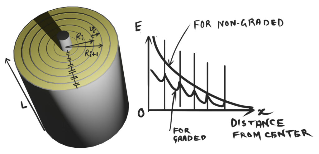
If we make the capacitance of each cylindrical capacitor equal, the voltage drop across each layer becomes equal. This uniform voltage distribution across the entire insulation thickness avoids localized high electrical stress. Therefore, it means the capacitor grading minimizes the chance of partial discharge.
There are mainly two types of condenser bushings, or capacitor graded bushings- OIP Bushing and RIP Bushing