Capacitor Element Winding
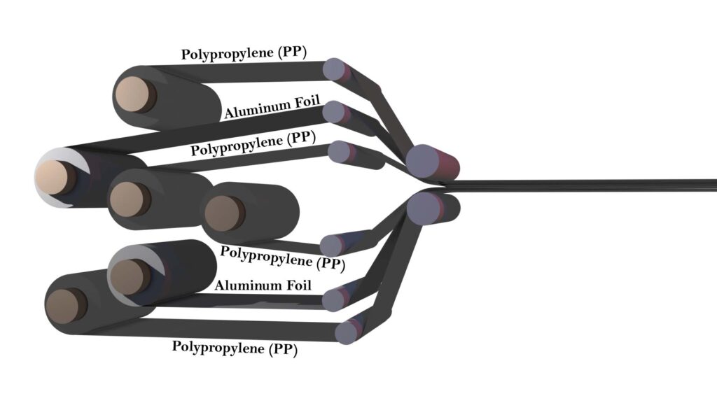
In the winding process, the material is wound using aluminum foil and polypropylene (PP). First, a layer of PP is placed, followed by a layer of aluminum foil. This layering continues step by step until the complete element is formed. Once the winding is complete, the element is tested on the spot using a 500-volt test. If it passes the test, it proceeds to the next stage of production.

Stacking and Strapping
Next is the stacking stage. For this, an installation board will be provided, which is designed based on the job specifications. In this stage, we use inner board and a fuse board for each element, although this is specifically for an internal fuse unit. For fuse less units, the fuse board are not required. The fuse wire is pasted onto the fuse board during this process. After the fuse element is installed in the boards, the components are stacked and strapped together. Hence the term “stacking and strapping” is used to describe this stage.
Stack Soldering
Once stacking is completed, the unit is loaded onto a conveyor, where trained soldering operators carry out the soldering process. This process is referred to as scrub soldering. To strengthen the soldered connections, a copper strip is added. Without this strip, there is a risk of the connection becoming loose. Insulation is provided specifically to separate the fuse wire from the aluminum. On top of the unit, a terminal board is placed, and on the bottom, a pressboard is added for additional insulation.
Stack Pressing
After that, the assembly goes through a pressing operation. A pressing machine applies a controlled amount of pressure. The pressure applied is adjusted according to the requirement of design. For fuse units, the required pressure is typically less than the pressure required for fuse less units. The pressing is to maintain uniform pack pressure, which is essential for consistent capacitance values. Capacitance depends on the distance between electrodes, and applying pressure helps maintain this gap uniform. This pressure ensures that the electrical characteristics of each element remain stable.
Soldering Fuse Wires
After pressing, the unit proceeds to the soldering stage. The fuse wire is bent and soldered to the appropriate terminals. Once soldering is completed, the unit moves to the wrapping stage.
Wrapping Stage
Here wrapping machines are used to wrap the unit using insulation paper to provide extra insulation. After wrapping, the final unit is loaded onto a conveyor for the drying stage.
Drying Stage
There are three drying mechanism chambers used to eliminate moisture from the components, with the induction heating system playing a central role. In the first chamber, eddy currents are induced within the aluminum foil, generating internal heat that raises the temperature and effectively removes moisture from both the polypropylene (PP) film and the aluminum foil. This direct induction heating is the primary method for moisture elimination at this stage.
Afterward, the unit proceeds to the second chamber, where it undergoes approximately five minutes of additional induction heating. Here, heat is applied externally, targeting the wrapping paper to remove any remaining moisture. Following this, the unit, now in the hot condition, is transferred to the third chamber. This is a vacuum chamber. This is for final moisture removal under reduced pressure. Once the vacuum drying process is completed, the dried material is loaded onto a conveyor and transported to the canning stage, where the final sealing or encapsulation of the components is carried out.
Canning Stage
After the vacuum drying process is completed, the unit moves to the canning stage. Canning refers to the process of placing the dried element assembly into a metal casing, commonly referred to as a can. These cans provide mechanical protection and ensure the integrity of the unit for subsequent handling and operation.
Soldering Top Plate Terminals
Once the assembly is inserted into the can the process continues with soldering the top plate terminals to the unit. An operator performs the soldering process to ensure secure electrical connections. After soldering, insulation papers are inserted around the terminal connections to enhance the insulation of the connection conductors. Once the insulation papers are in place, the can is sealed through a welding process. The robotic welding process may be used in modern manufacturing unit for the purpose.
Nitrogen Leak Test
After the canning and welding processes are completed, each unit undergoes a nitrogen (N₂) leak test to ensure sealing integrity. This test is performed on all units to detect any potential leakage, especially important before the oil impregnation process. Only units that pass the N₂ leak test are connected to the impregnation manifold.
Oil Impregnation Process
Once connected, the units are first subjected to vacuum evacuation until the internal pressure reaches the required level. This vacuum condition is maintained to ensure the complete removal of air and moisture form the can. After achieving the desired vacuum level, the oil impregnation process begins. The impregnation is held for at least 20 minutes to ensure complete penetration of oil into the internal components, thereby eliminating any hollow spaces and ensuring dielectric reliability.
The unit is connected to the manifold tool using two hoses. One is large hose and one small hose. The larger hose is designated for vacuum application. During the initial phase, vacuum is applied through the large hose while the small hose remains closed. This vacuum process continues until the desired vacuum level is achieved. Once the target vacuum is reached, the vacuum path is closed, and the small hose is opened to allow oil impregnation. Oil then flows through the small hose and is absorbed into the unit under vacuum, ensuring proper impregnation of internal components.
Final Sealing
After the oil impregnation process is completed, a locking nut is used to block the opening that was used during oil filling. At this stage, inspections are conducted, followed by the final sealing operation. The sealing ensures that the unit remains closed and leak-proof. Once sealing is finalized, the unit is sent for a heat soak test. During this stage, the unit is subjected to elevated temperatures to check for any possible leakage issues. If no leakage is detected during the heat soak, the unit is cleared to proceed to the next stage, which is electrical testing.
Painting Stage
After completing 100% electrical testing, the unit is approved for painting. Only those units that pass all routine tests proceed to the next stage. Here, the unit undergoes shot blasting followed by painting to ensure proper surface finish and corrosion protection. Actually, after shot blasting, some porosity will be created on the surface. This porosity helps the paint adhere better and prevents it from peeling off immediately.
What is shot blasting?
Shot blasting is a process where small metallic shots are blasted onto the surface of the can. These metal balls are shot at high velocity and strike the surface, much like tiny hammers. This impact creates a rough texture on what was originally a smooth surface. If we apply paint on a flat surface, there’s a higher chance it will peel off quickly due to poor adhesion. But by introducing this porosity, the paint sticks better and the coating becomes more efficient and durable. So, this process improves both adhesion and longevity of the paint.


