A watt-hour meter-type induction relay is essentially a variant of an electromagnetic induction relay. Instead of only current or only voltage, it operates depending on the power input to the relay. Obviously, these relays require both the voltage and current of the system to operate.
Power is the product of voltage, current, and power factor \(cos \theta\). Here, the torque is directly proportional to power. So the torque depends upon the power factor. If the power factor is negative, then the torque is also negative. Thus, the direction and strength of the torque depend on the phase displacement between the system voltage and current. That is why a wattmeter-type induction relay serves the purpose of power directional protection.
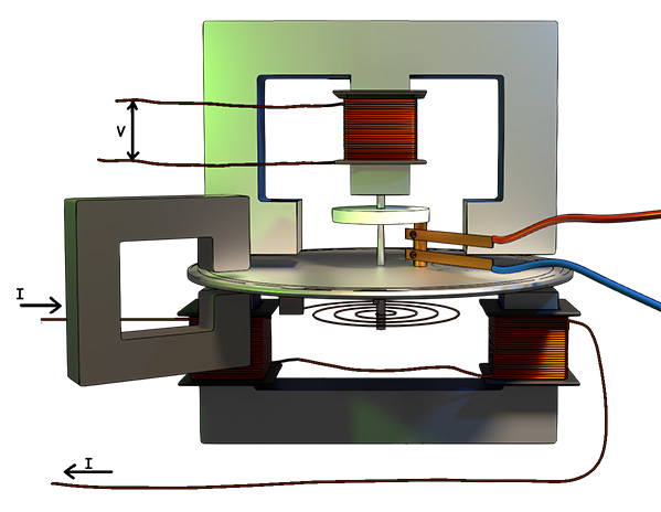
Construction of a Watt-Hour Meter Type Induction Relay
Aluminum Disc
Obviously, this relay essentially has a lightweight aluminium disk. Aluminium is the most preferred metal for the disk because of its lightweight and non-magnetic nature. A spindle at the center of the relay holds this aluminium disk. This aluminium disk can freely rotate about the spindle. The spindle carries a moving contact.
Current Coils and Magnet
Below the aluminium disk, there is an electromagnet. Two limbs of the core of that electromagnet hold the current coils. These two coils are connected in series. We inject system current into this coil to create flux proportional to the system current. We do this by connecting the current transformer secondary circuit with the coils.
Voltage Coils and Magnet
At the same position, just above the aluminium disk, there is another electromagnet. This electromagnet has a typical three-limb structure. The central limb of the core of the electromagnet holds the voltage coil. We connect this voltage coil across the protected circuit through a potential transformer. In other words, we connect this voltage coil across the secondary of a potential transformer.
Other Attachments
Here, we use a permanent magnet to provide braking torque or damping to the movement of the relay. A spiral flat spring is attached to the spindle below the aluminium disk. This spring provides the restoring torque to the relay, preventing unnecessary movement of the disc before the operating torque reaches its threshold value.
Additionally, when the relay operates and the fault becomes cleared, the operating torque drops below the restoring torque of the spring. As a result, the spring reforms to its normal shape and pulls back the disk to rotate, returning to its normal non-operated condition.
Once the product of current, voltage, and power factor of the system crosses the threshold limit, the disk starts rotating. Consequently, it closes the ‘NO’ contact. Once the contact closes, the system protection is initiated. Finally, the circuit breaker clears the fault from the system.
Consequently, the input power to the relay comes down. Therefore, the disk rotates to return to its normal open position due to the restoring torque of the flat spiral spring.
Working of the Watt-hour Meter Type Induction Relay
The watt-hour meter-type induction relay works on the electromagnetic induction principle. Obviously, it works like a Ferraris induction watt-meter or energy meter. It produces rotational torque due to the rotating magnetic field. However, instead of measuring energy, it closes the NO contacts of the relay due to the rotation of the disc.
The relay has two electromagnets. The secondary of the potential transformer feeds the upper electromagnet. At the same time, the current transformer feeds the lower electromagnet. These two magnets produce two alternating fluxes.
Development of Torque
Say, ‘I’ is the current passing through the coil of the lower electromagnet. As a result, this current produces the magnetic flux \(\phi_I\). So, this flux is directly proportional to the system line current. This flux \(\phi_I\) will also be in phase with the system line current.
The PT secondary feeds the upper electromagnet. Therefore, this electromagnet produces another flux, denoted as \(\phi_V\). Obviously, this \(phi_V\) is directly proportional to the system voltage.
The number of turns in the voltage coil attached to the upper electromagnet is quite high. Therefore, this coil offers high inductance. As a result, the voltage coil flux (\(\phi_V\)) lags the voltage V approximately by 90 degrees.
Thus, the current flux and voltage flux are phase-displaced.
Additionally, we mount the current coils and voltage coils on spatially displaced limbs. Due to both time displacement and space displacement, the fluxes combine to produce a rotating magnetic field.
This rotating magnetic field moves around the aluminium disk. Therefore, it continuously cuts the aluminium disk. Obviousely, this flux cutting produces eddy currents on the disc.
Now, due to the interaction of this eddy current with the fluxes, a torque is developed at the edge of the disc. The disc then begins to rotate due to this torque. Obviously, this torque is directly proportional to \(V\times I \times \cos\theta\).
Directional Nature of Watthour Meter Type Induction Relay
Here you see that the direction of the torque also depends on the value of \(\cos\theta\). In other words, it depends on the angle between voltage and current.
If \(\cos\theta\) has a positive value, the torque will be in one direction. Again, when \(\cos\theta\) becomes negative, the direction of the torque reverses. Therefore, a watt-hour meter-type induction relay can sense the direction of the power. The direction of rotation of the relay disc depends on the direction of the power flow.
Because the torque takes time to accumulate, this relay provides a natural time delay.
Damping
We place a permanent magnet near the disc. When the disc rotates, it cuts the magnetic field of the permanent magnet. Due to this flux cutting, the magnetic field induces eddy currents on the disc. These eddy currents are different from the main eddy currents. This eddy current tries to oppose the cause of the production of that eddy current as well. Obviousely, the ultimate cause of this eddy current by the permanent magnet is the relative motion of the disk with respect to the magnetic field.
So it tries to stop the rotating disk. This is how the permanent magnet produces braking torque on the disc. Braking provides smooth operation, stable resetting, no overshoot, and no oscillation.
Restoring Torque
The flat spiral spring attached to the spindle provides the restoring torque. When the operating torque increases, the disk begins to rotate. Due to the rotation of the disk, the spiral spring twists. Therefore, it provides restoring torque. When the operating torque exceeds the restoring torque, the disk moves forward to close contacts.
After clearing the fault, the power drops to its normal value. As a result, the restoring torque of the spring pulls the disk back to its initial position, and this is how it becomes ready for the next operation.