Power systems deliver electricity from generation stations to consumer ends. Nowadays, power system networks become very complex. This increased complexity disrupts the voltage and frequency. Hence, the system needs to maintain voltage and frequency to ensure reliable and efficient power flow. For example, changes in load, major faults, switching operations, and renewable energy integration can cause voltage drops. These also cause flickers, harmonics, and other power quality issues in the system.
Reactive power is the power that does not perform any useful work. However, the system needs to maintain the reactive power to maintain the voltage level. Voltage stability refers to the ability of a power system to maintain acceptable voltage levels.
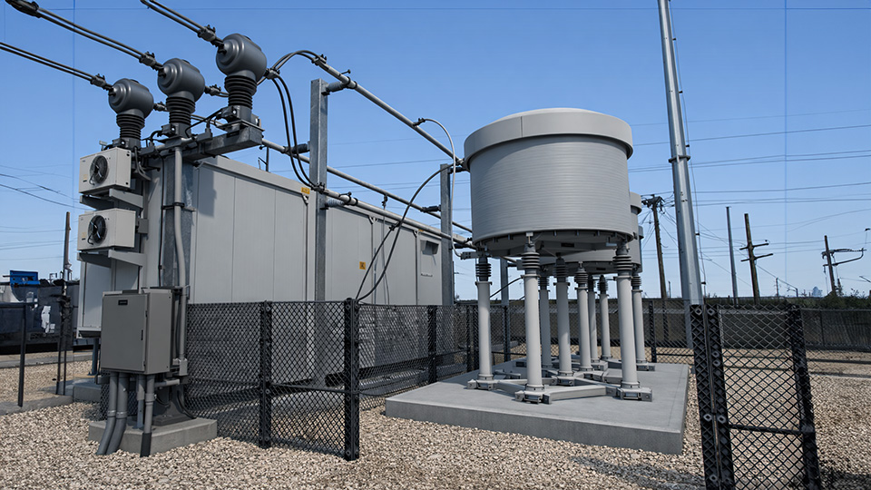
What are STATCOM Devices?
A STATCOM device is shunt-connected with a power system bus or line. It is easily proved from the expression for voltage regulation of transmission lines that the system voltage depends on the quantity of reactive power in the system. Therefore, to maintain system voltage stability, the quantity of reactive power in the system needs to be controlled.
A STATCOM device uses power electronics to generate or absorb reactive power needed to maintain the reactive power level. STATCOM has a voltage source converter (VSC) as its main part that converts a DC voltage at its input to an AC voltage at its output. STATCOM can control the magnitude and phase of the output AC. By varying the output voltage of the VSC, STATCOM can inject or draw reactive current from the network. Thus, the STATCOM acts as a controllable capacitor or inductor.
Dual Nature of STATCOMS
When there is a lack of reactive power in the system, the system voltage may rise above the normal voltage level due to the capacitive nature of transmission lines. In that case, the STATCOM behaves like a shunt reactor and absorbs the capacitive reactive power. In other words, it absorbs the required reactive power from the system to bring the voltage level back to the normal range.
On the other hand, when there is excessive inductive reactive power in the system, the voltage becomes lower than the normal range. In that condition, the STATCOM behaves like a shunt capacitor and supplies capacitive reactive power to the system. This neutralizes the inductive reactive power and brings the voltage level back to the normal range.
Why does STATCOM match the Phase Angle?
In STATCOM, there is a voltage source converter (VSC). This is the main component. In VCS, there is an IGBT or GTO-controlled mechanism.
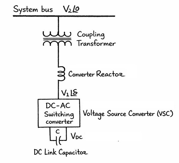
Also, there is a reactor between VSC and the system bus. This is the coupling device. Often, we use a transformer as the reactance between the bus and the VCS. The VCS receives DC power from a source. Then it converts it into a sinusoidal AC output with the power frequency. It also adjusts the phase angle of the converted AC signal based on the feedback from the system bus power. It always matches the phase of the converted AC exactly with the bus voltage. Now, the question is why it needs to match the phase angles between VCS and bus voltage. To answer it, we need to go through the basic voltage equation for a STATCOM.
Voltage Equation of STATCOM
Say V1 is the converter voltage, and the coupling impedance is R + jX. At the same time, the bus voltage is V2. Let us take the bus voltage as our reference voltage. V1 , along with angle , is the VSC voltage. Hence, it is nothing but the output voltage of STATCOM. So, we can write:
So, the voltage difference between the voltage source converter and the bus is
That becomes,
Now, the current flowing through the reactor between the VSC and the bus is:Since R is very small compared to the reactance, we can neglect the resistance R.
So, we can write:Now, the total complex power is:So,Here, V2 is the receiving-end voltage, so this gives the receiving-end power.
After simplifying the expression, we get,andHere, P is the real power and Q is the reactive power. Now, if the STATCOM makes delta () equal to zero, then sin0 = 0 and cos0 = 1. So, the real power becomes zero. In that case, only reactive power is exchanged, and we can write it as: This shows that reactive power depends on the difference between the bus voltage and the converter voltage. If V1 > V2, reactive power flows from STATCOM to BUS. Again, when V2 > V1, reactive power flows from BUS to STATCOM. This is the basis of reactive power control by a STATCOM.
Video on the Voltage Equation of STATCOM
Construction and Components of STATCOM
Voltage Source Converter (VSC)
The voltage source converter (VSC) is the main component of a STATCOM. It receives DC voltage either from a DC capacitor bank or a DC source. It converts this DC voltage into a three-phase AC voltage signal. The output AC voltage matches the magnitude, frequency, and phase angle of the power system voltage. The VSC is basically an inverter. It converts DC power into AC power. Obviously, it is a static device. It uses either GTO or IGBT switches. That is why we call it a “static” compensator. However, the IGBT-based PWM inverter is the most commonly used type.
DC Link Capacitor
The next vital component is the DC link capacitor. This capacitor keeps the DC voltage almost constant. It also keeps the DC voltage ripple-free. STATCOM generally does not provide active power. So, it does not require a large DC power supply. The DC link capacitor is sufficient for this purpose. However, sometimes a battery bank is used. It helps to deliver active power to the bus when required.
Converter Reactor
Next comes the converter reactor. This reactor limits the converter current. It also reduces system harmonics. Continuous switching of IGBTs produces harmonics. So, the converter reactor is needed to reduce these harmonics.
Coupling Transformer
The last major component is the coupling transformer. It connects the STATCOM to the power system bus. The transformer is required for voltage matching. It also provides electrical isolation between the bus and the converter. The transformer also helps in reducing harmonics.