Before discussing the types of sheath bonding used in high voltage cable let us recall our knowledge regarding sheath and cause of induced voltage and current in the sheath of a HV cable. Actually, all types of bonding are used to limit the unwanted, induced voltage and current in a cable sheath.
What is a Cable Sheath?
Before discussing the importance of a cable sheath, let us first understand what it is. A cable sheath is the outer covering of a cable that basically protects the conductor and insulation from damage. It can be made of metallic materials like lead, aluminum, or copper, or non-metallic materials like PVC.
Now, why is a cable sheath used?
It is easy to understand why a non – metallic cable sheath is used. Also, it is used for protecting the cable from physical damage like cuts, bends, and impacts. It also prevents moisture from entering the cable, which could harm the insulation. The non-metallic materials, like PVC is much more economical to use as a cable sheath compared to a metallic sheath, but we need to use a metallic cable sheath in high voltage systems. It will be well understood if we go through the advantages of the metallic cable sheath one by one.
- A metallic cable sheath also protects the cable from physical damage like.
- It also prevents moisture from entering the cable, just like a PVC sheath.
- The external magnetic fields can affect the performance of the cable. Electromagnetic interference may also cause disturbances to nearby telecommunication lines. A metallic sheath acts as a shield to control the electric field and reduce electromagnetic interference.
- A metallic sheath is always connected to the earth, providing a path for fault currents to safely reach the ground.
- Since the heat conductivity of metal is very high, it easily absorbs the heat generated in the conductor through the insulation layer. It also facilitates the transfer of heat to the surrounding soil.
Why is sheath bonding required for a high-voltage cable?
Sheath bonding means connecting the metallic sheath of a cable to the ground. When current flows through a high-voltage cable, it creates a magnetic field around it. This magnetic field can induce voltage and current in the metallic sheath. If not controlled, this induced voltage and current can cause power losses, overheating, and damage to the cable. Sheath bonding helps to limit the induced voltage and current in the sheath. Also, it protects the cable from external electromagnetic fields. Without proper bonding, the cable can even affect nearby communication lines. Sheath bonding provides a smooth path to the fault current to ground.
What are the types of Sheath Bonding in High Voltage Cable?
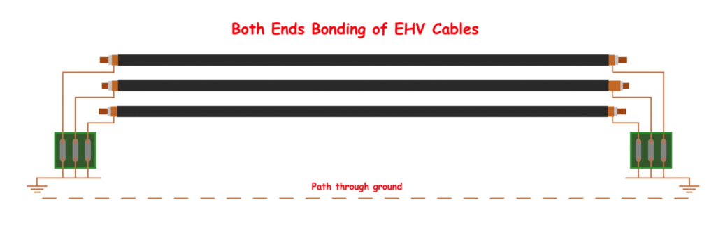
Both Ends Bonding
If the metallic sheath is connected to the ground, the problem of induction might be solved. Connecting both ends of the cable sheath to the ground. This is the simplest way of sheath bonding used for the purpose. But it creates unnecessary circulation of induced current. That causes heating and power loss. This extra heating causes de-rating of the cable. But for very short length cables, preferably below 500 m, the sheath resistance is insignificant. Hence, heating due to induced current are negligible. So, for short-length cable laying, the both-end bonding method is acceptable. Here, both ends of the sheath are solidly connected to the earth.
Single End Bonding
There is a big problem at both ends of bonding. The problem is the circulating current. Due to the mutual induction effect, there will always be an induced current circulating between the sheath and ground. This current may create unnecessary heat. Due to this heat, the cable can be de-rated. Here, the necessary earthing of the sheath is done only at one end of the sheath. The other end of the cable sheath is kept open.
As one end of the sheath is kept open, there is always an induced voltage at this end. For normal condition this induced voltage is under a tolerable limit. Although when any major fault current passes through the conductor of the cable, there may be dangerously high voltage induced at the open end of the sheath. This high voltage may harm the insulation of the cable. Also, this high voltage may create a problem for step voltage and touch voltage limits.
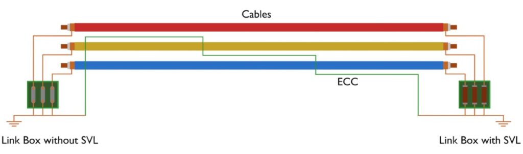
Use of SVL and ECC
For these reasons, we connect an SVL (Sheath Voltage Limiter) between the sheath and ground at the open sheath end.
This sheath voltage limiter is nothing but a lightning arrester of a very low voltage level. The limiter (SVL) conducts when there is a high voltage induced at the open end of the sheath. For a normal induced voltage, an SVL does not conduct. In this way induced high voltage effect on the insulation during a fault can be avoided.
In single-end bonding, one earth continuity conductor ECC is also used between the two ends of the sheath. The main purpose of this ECC is to provide a parallel path for the sheath. During a fault, the maximum percentage of induced current will pass through the ECC instead of the cable sheath. Therefore, the induced voltage on the sheath is reduced. Another purpose of ECC is to provide the return path for the fault current to the main substation earthing grid system.
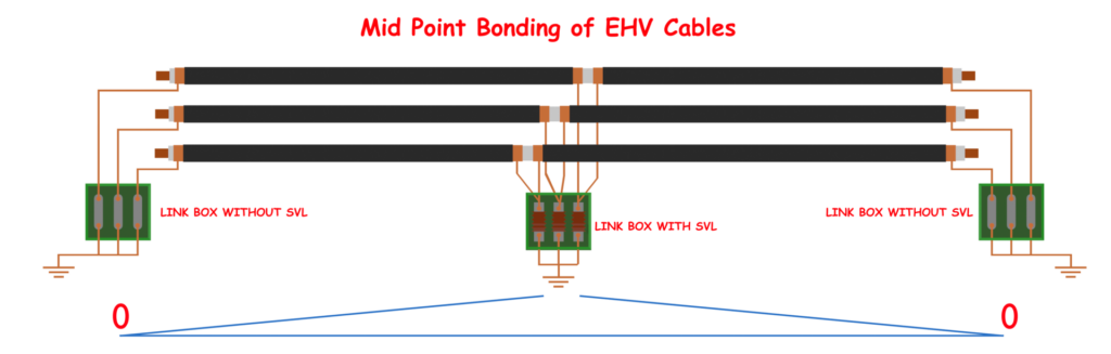
Mid Point Bonding
Both-end bonding is a simple way to connect both ends of the cable sheath to the ground. But for long cables, it has some disadvantages due to the sheath impedance. The significant sheath impedance causes significant voltage build-up at the middle of the cable sheath. Also, the induced circulating current causes significant heat.
So, in this method, the sheath is grounded at the mid-point of the cable length, while both ends remain insulated from the ground. This way, the cable sheath is divided into two halves. Each half has its own induced voltage, but since both ends are open, there is no continuous current flow in the sheath.
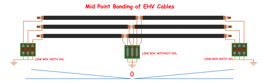
The key point here is that the induced voltage at each half is much lower compared to the total length of the cable. As a result, the problem of high induced voltage at the ends (like in single-end bonding) is reduced. Also, since there is no direct connection at both ends, circulating current is avoided, which solves the problem seen in both-end bonding for long cables.
But still, for very long cable lengths, the induced voltage in each half may not be negligible. In such cases, Sheath Voltage Limiters (SVLs) can be used at the open ends to protect the sheath from transient overvoltages. So, mid-point bonding provides a balanced solution, especially for medium-length cables, where both-end bonding causes high losses, and single-end bonding causes high induced voltage at one end.
Cross Bonding
Mid-point bonding balances these two by grounding the sheath at the center, reducing voltage build-up and avoiding continuous currents. However, for very long cables, even mid-point bonding may not be enough. The cross-bonding is a more advanced method used for long, high-voltage cables. In cross-bonding, the cable length of all three phases is divided into three equal sections. The metallic sheaths of these sections are connected in such a way that the vector sum of the induced voltage in all three sections is zero or very close to zero. This is done by connecting the sheath of one section to the sheath of another section of the next phase in a crossed manner.
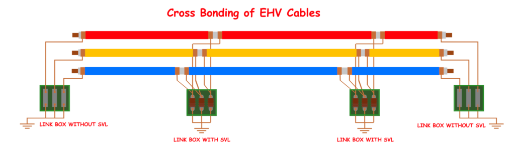
Practical Example
For example, in three-phase systems, there are three cables, each carrying one phase of the current – Phase R, Phase Y, and Phase B. The total length of each cable is divided into three equal sections. The sheath of R Phase in the first section is connected to the sheath of Y Phase in the second section, and then to the sheath of B Phase in the third section. Similarly, the other two phases are also cross-connected in a similar pattern. Every cross-bonding point is connected to the ground with SVLs.
Since the induced voltages are 120° apart from each other, the total induced voltage is ideally zero along the entire cable length. Also, there is no continuous current flow in the sheath, so no extra heating or power loss occurs. The cable can carry more current without being derated due to sheath losses.
However, cross-bonding is more complex than other methods. It requires proper planning and installation. Special joint boxes are needed at the points where the sheaths are cross-connected. But for long cables, especially those above 1 km, cross-bonding is the best choice. It avoids the disadvantages of both-end bonding, single-end bonding, and mid-point bonding, making it suitable for high-voltage power transmission over long distances.