Power Transmission Utilities use lattice-structured transmission towers for extra high voltage transmission lines and ultra-high voltage transmission lines, normally above 33 kV or including 33 kV lines. They use galvanized iron or GI angles with nuts and bolts to erect the electrical transmission towers. The height of these towers ranges from 20 to 40 meters, or even above, as per requirements. In addition, they use exceptionally long transmission towers for river crossings and hilly areas. These towers must be capable of holding the weight of the heavy transmission conductors. Additionally, they must be capable of withstanding the huge tension imposed by the conductors on the tower at the tension point.
Basic Structure of Transmission Towers
The ratio of the height to the width of the base of the tower normally varies from 3 to 7. The area of the base of the tower depends on different factors. Those factors are the condition of the soil on which the tower is to be erected, the height of the tower, and the wind pressure. It also depends on the inclination of the land on which the tower is to be erected.
Types of Transmission Towers
As per Indian Standards, we segregate the types of towers into four categories, such as,
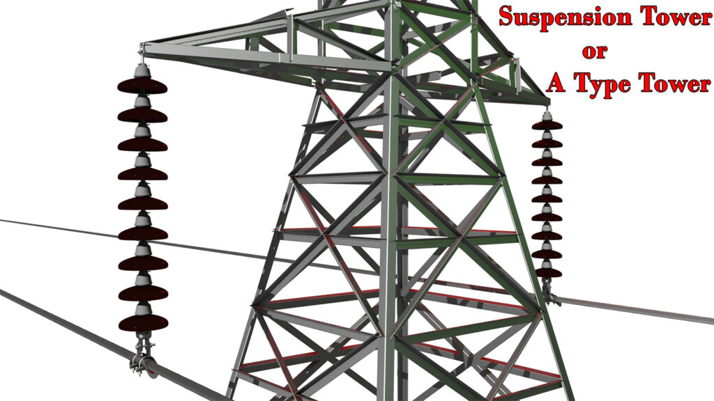
A-type Towers
These towers only hang the conductors without any additional tension except the weight of the conductors and the wind pressures. We also refer to this type of tower as suspension towers. The base area of these towers is not so large as compared to other types of towers. This is because these towers do not have to sustain the horizontal tension of the conductor. These towers mainly deal with the vertical force due to the weight of the conductor. When the line goes in a straight line without any crossing or termination, these towers serve the purpose. It allows only up to \(2^{\circ}\) deviation of the transmission line.
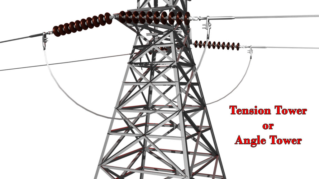
B-type Towers
These towers are angle towers. When the line diverts from \(2^{\circ}\) to \(15^{\circ}\), we use this type of towers. Obviously, due to the angle of deviation, the conductor must not be continuous. So, the conductors of the circuit terminate at this tower from both sides. So, this is a kind of tension tower. The base of the B-type tower is wider than that of the A-type tower.
C-type Towers
When the angle of diversion of the transmission line becomes \(15^{\circ}\) to \(30^{\circ}\), the base of the tower becomes wider. We refer to these towers as C-type towers.
D-type Towers
When the angle of diversion is \(30^{\circ}\) to \(60^{\circ}\), we use D-type towers. This tower occupies the largest base area. Therefore, it can withstand the maximum horizontal tensile strength of the conductor. These towers also serve the purpose of dead-end towers. That means we can use a D-type transmission tower at the termination point of a transmission line. That means at the beginning and end of the transmission line, there must be a D-type tower. Also, when the angle of diversion is more than \(30^{\circ}\) but below \(60^{\circ}\), we use D-type towers. Additionally, at rail crossings, we normally use D-type towers irrespective of the angle of diversion.
Mechanical Strength of Electrical Transmission Towers
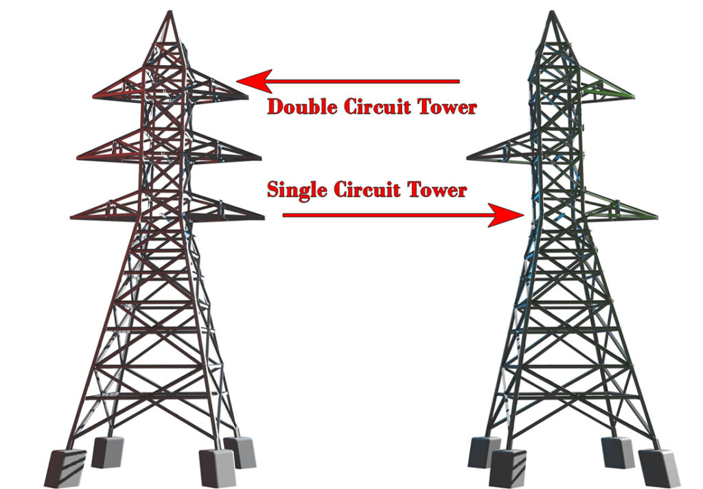
Think about a double circuit tower or DC tower. Each of the towers carries a total of six conductors. That means, three conductors per circuit, or in other words there is a single conductor per phase. Obviously, each of the towers has to withstand the tension and load of the conductors. In addition, the tower must sustain the abnormal condition of unequal tension due to conductor snapping.
If a single conductor of either circuit is snapped, A-type and B-type towers must be capable of withstanding this unequal distribution of tension. When two such conductors snap, the C-type tower can withstand that unequal tension. Again, when three conductors of any circuit snap together, a D-type tower must be capable of withstanding that unequal tension also. I mean, it will stand upright without bending or falling at that abnormal condition too.
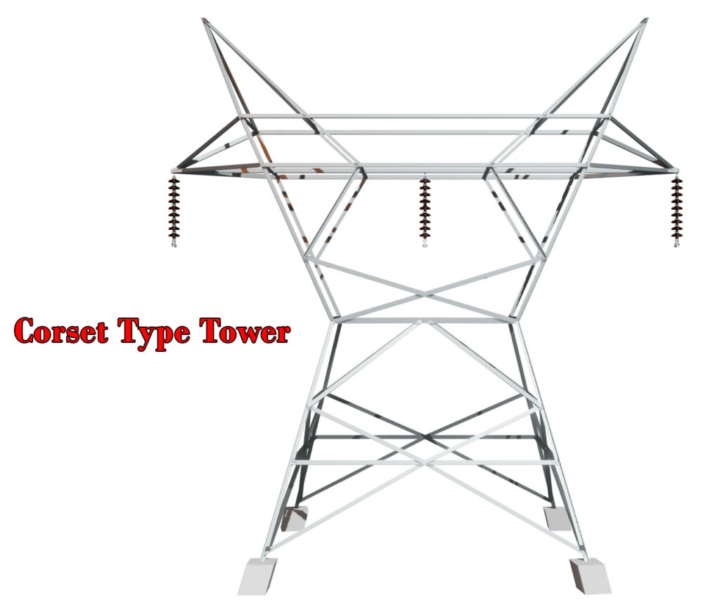
Corset Type Tower
Normally, for 66kV, 132 kV, and 220 kV transmission lines, the phase conductors of each circuit are oriented in a vertical configuration. However, for 220 kV, 400 kV, and 765kV lines, the power utilities also use a special type of single circuit towers. These towers hold the conductors in horizontal configurations, as shown in the figure above. We refer to this type of tower as a corset-type tower. This type of tower requires less GI angle and can withstand more torsional force than the normal tower due to its wider design.
Dimensions of Angle used for Tower Structures
As per the Indian Standard, any angle used in the leg parts of an electrical transmission tower under the ground should not be less than 6 mm thick. Any angle used above the ground for the tower structure should not be less than 5 mm thick.