Before we discuss the use of disc insulators in high-voltage transmission lines, let’s understand the need for such insulators.
Transmission lines operate at very high voltages such as 66 kV, 132 kV, 220kV, 400 kV, even 765 kV and more. So, the conductors used in these systems are also very heavy. To maintain proper ground clearance, we suspend these conductors from tall transmission towers made of iron or steel. Since these towers are at ground potential, we must electrically insulate the high-voltage conductors from the tower body. This calls for strong and reliable insulation between the conductor and the tower.
Need for Disc Insulators
If we tried to use a single, long, and heavy insulator, it would be challenging to manufacture, transport, and handle such a unit. This challenge led manufacturers to develop disc insulators.
A disc insulator is a modular insulating unit. We can connect multiple disc insulators in series to form a string. This string provides insulation according to the required voltage level. Each disc is small, lightweight, and easy to manufacture, transport, and install.
Construction of a Disc Insulator
Each disc insulator consists of three main parts.
Socket Cap
The top part is a metal socket cap that is shaped as a cap with a groove. Manufacturers typically use galvanized cast iron for this part. After casting, the cap undergoes galvanization to prevent corrosion.
Insulator Body of Disc Insulators
The body of the disc has an umbrella-like shape. This design helps keep the lower surface dry during rain. The body has a projected portion at the top, which fits into the socket cap. Manufacturers use special cementing materials to fix this part firmly inside the cap. They treat the joint specially to ensure it can withstand mechanical loads without detaching.
The bottom surface of the disc has several concentric parallel grooves. These grooves increase the creepage distance and improve electrical performance.
Ball End
The bottom part of the disc has a hole where manufacturers insert a metal ball fitting. They also use cement to fix this ball securely. The ball size is standardized, with common diameters being 16 mm and 20 mm.
Forming Strings of Disc Insulators
We join disc insulators by inserting the ball of one unit into the socket of the next. A locking pin passes through a hole in the socket to hold the ball in place. After insertion, we bend the pin to lock it securely. In this way, we connect multiple discs one after another to form a string of the desired length based on voltage requirements.
Types of Disc Insulator Strings
There are three main types of strings.
Suspension String
This string hangs vertically from the tower cross-arm. It supports the vertical weight of the conductor.
Tension String
This string is installed horizontally. It holds the tensile force of the conductor.
Anchor or Pilot String
We use this type in special conditions. We use it very rarely in common applications.
As per standard practices, we use a specific number of disc insulators in a string based on the voltage class and type of application (suspension or tension). For example, 33 kV, 66 kV, 132 kV, 220 kV, and 400 kV lines require a specific number of discs, which is typically mentioned in standard tables.
Types and Materials of Disc Insulators
Disc insulators are made using the following materials:
Porcelain Disc Insulators
Glazed porcelain is widely used due to its availability and low cost. It offers good dielectric strength (typically around 2–3 kV/mm) and strong mechanical performance.

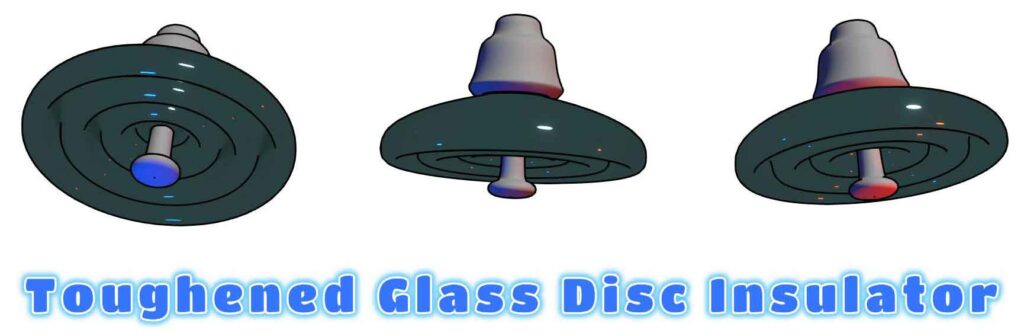
Glass Disc Insulators
Many modern disc insulators are made of toughened glass. This material has several advantages. It has a higher dielectric strength (6–9 kV/mm), about twice that of porcelain. Transparency allows easy detection of voids, air bubbles, or foreign particles. The good corrosion resistance makes it ideal for coastal or polluted environments.
However, one disadvantage is that the top surface can retain water, which may lead to problems. Still, many utilities prefer toughened glass over porcelain in challenging environments.
Standardization and Technical Particulars of Disc Insulators
Manufacturers follow standard dimensions and designs to ensure interchangeability and reduce dependence on a single vendor. A typical disc insulator has a diameter of 255 mm. The height from the socket top to the ball bottom is 145 mm. The manufacturers maintain a standardized creepage distance, but it can vary based on agreement.
| Parameter | 400 kV | 220 kV | 132 kV | 33 kV |
|---|---|---|---|---|
| Creepage Distance per Disc (mm) | 430 | 430 | 430 | 430 |
| Height / Distance Between Units (mm) | Tension: 170 Suspension: 145 | 145 | 145 | 145 |
| Diameter (mm) | Tension: 280 Suspension: 255 | 255 | 255 | 255 |
| Mechanical Strength (kN) | Tension: 160 Suspension: 120 | Tension: 120 Suspension: 70 | Tension: 120 Suspension: 70 | Tension: 120 Suspension: 70 |
| Number of Discs in String (Line) | Tension: 24 Suspension: 23 | Tension: 15 Suspension: 14 | Tension: 10 Suspension: 9 | Tension: 3 Suspension: 3 |
| Number of Discs in String (Sub Station) | Tension: 25 Suspension: 23 | Tension: 16 Suspension: 15 | Tension: 11 Suspension: 10 | Tension: 3 Suspension: 3 |
| Ball Diameter (mm) | Tension: 20 Suspension: 20 | Tension: 20 Suspension: 16 | Tension: 20 Suspension: 16 | Tension: 20 Suspension: 16 |
There are two major types based on surface design. These are Normal Disc Insulators and Antifog Disc Insulators. The antifog type has a larger creepage distance, typically around 432 mm, and is used in high-pollution areas.