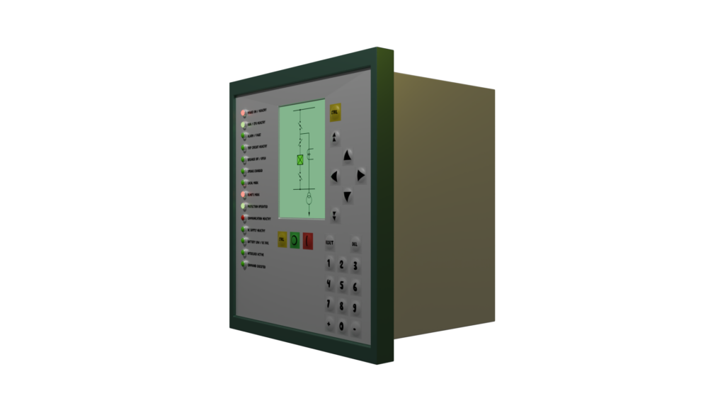
A Bay Control Unit (BCU) is nothing but a specialized Intelligent Electronic Device (IED). We use it electrical substations to monitor, control, and protect different equipment like circuit breakers, disconnectors, and transformers, etc. It acts as an interface between the substation hardwired equipment and the HMI (Human Machine Interface). The BCU receives current voltage signals, transduced analog signals and open close contact status from the equipment. It processes these signals and sends through IEC 61850 communication standard protocol for modern substations. It also converts the control or operational signals coming from remote or local HMI through IEC 61850 protocol for physical operations of the equipment.
Below is a breakdown of its core functional modules.
Central Processing Unit or Core Processing Unit
This is the brain of the Bay Control Unit. This is the central processor. This executes all control, operation, interlocks and communication logic. The modern BCUs utilize 32-bit or even 64-bit processors. Even, some units utilize dual-core processors for better redundancy. More sophisticated BCUs use industrial-grade Intel Atom CPUs (e.g., 1.6 GHz).
Memory of BCU
For real-time data buffering and operating system functions Bay Control Units generally use 512 MB RAM.
Modern BCUs use 512 MB solid-state disks (SSD) for storing the firmware, operating system, application logic, and historical event logs.
The Non-Volatile Memory (ROM) stores the configuration files, fault records, and counters.
A Real-Time Clock (RTC) provides time-stamping for all events and faults, often synchronized via GPS/SNTP for system-wide consistency.
Inputs
Current Voltage Input Modules
An Analog Input Module interfaces voltage and current from VTs and CTs, respectively. Normally, a Bay Control Unit accepts secondary currents and voltages as analog inputs directly from CTs (Current Transformers) and VTs (Voltage Transformers). Then the BCU uses 16-bit high frequency Analog-to-Digital Converters (ADCs) to digitally sample the incoming signals.
DC Analog Inputs of BCU
To monitor external transducers (e.g., temperature, pressure, battery voltage), BCUs also include DC analog inputs (e.g., 4–20mA or 0–10V).
Binary Input/Output Module
This module only receives and sends discrete binary signals. It serves as a physical interface for controlling switchgear and sensing discrete statuses of equipment.
Binary Inputs (BI)
High-voltage isolated inputs (e.g., up to 124 channels) that read the status of circuit breakers (open/closed), disconnectors, earth switches, and alarms. The BCU receives the status of potential free contacts from different equipment.
Binary Outputs (BO)
Binary outputs (e.g., up to 38 channels) send open or close commands to circuit breakers and disconnectors.
Communication Interface Module of a BCU
The BCU uses multiple protocols and ports to talk to station-level devices, other bays, and the process level.
Station Bus
This is the primary link to the local HMI (Human-Machine Interface) to SCADA. IEC 61850 (MMS), IEC 60870-5-103, DNP3.0, Modbus.
Physical: 10/100Base – TX copper Ethernet or 100Base – FX optical fibre ports.
Process Bus
- GOOSE (Generic Object Oriented Substation Event): For high-speed peer-to-peer communication (e.g., tripping a remote breaker in 4ms). Supports IEC 61850-8-1.
- Sampled values (SV): Receives digitized current/voltage data from Merging Units (IEC 61850-9-2).
Redundancy Protocols: To ensure zero downtime, BCUs support redundancy standards like PRP (Parallel Redundancy Protocol) and HSR (High-availability Seamless Redundancy).
Serial Ports: RS-485 ports for legacy device integration or GPS clock synchronization.
Power Supply Module of a BCU
A Bay Control Unit operates on substation DC system. It is normally, 220V DC.