In our previous article, we discussed how an inductor behaves in a DC circuit. In this article, we shall discuss how an inductor behaves in an AC circuit.
Suppose there is an inductor. We have connected this inductor across an alternating electrical source. The alternating source generates a pure sinusoidal signal. Now, we shall consider an instant when the source current crosses zero. Just after that instant, the current increases to the positive peak. Therefore, the flux created in the inductor also rises from zero. Again, we know from our basic knowledge that the rate of change of the current across the zero crossing is maximum.
Therefore, the rate of change of self-linkage flux is also maximum at this instant. Again, we know that the induced emf across the inductor is directly proportional to the rate of change of flux linkage. Obviously, this is according to Faraday’s law of electromagnetic induction. Therefore, the voltage of the circuit obtains its maximum when the current has a zero value.
Again, we know that at the maxima of current, the rate of change of current is zero. Therefore, the rate of change of flux linkage is zero here. Hence, at that instant, there is no voltage induced across the inductor. As a result, the circuit voltage becomes zero.
After that, the current starts decaying, and hence, the rate of change of flux again increases. As a result, the induced voltage starts increasing. At zero crossing, the rate of change of current, that is, the rate of change of flux, becomes maximum. Hence, at that current zero crossing, the voltage again becomes maximum.
Again, from the current waveform, we can easily show that the voltage leads the current by . Alternatively, we can say the current leads the voltage by .
Analyze the Waveform
- Suppose the expression of the instantaneous current is given by, .
- Therefore, induced emf .
- Again, .
- So, we can write,
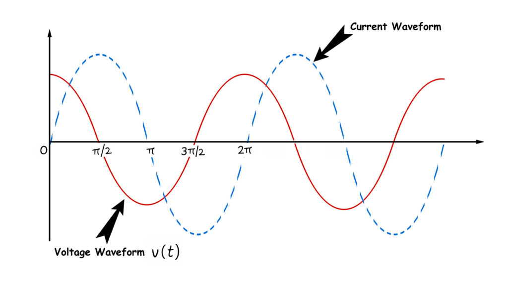
So, current has a sine wave, and the voltage varies with a cosine rhythm. Therefore, if we plot the sine current and the cosine voltage, we can see that the current lags the voltage by .
- At the origin, the current is zero, and the voltage is maximum because .
- For an angle , current gets its positive maxima because . At the same time, , hence induced voltage becomes zero.
- Aging at, , current crosses zero. Since , the voltage gets negative maxima.
- After that at. Therefore, the current comes to its negative maxima, and the voltage crosses zero.
Let us draw the waveform of the current and voltage of that inductor.
Methametical Prove
We have already considered the expression for current as . Where, ‘‘ is the maximum amplitude of the sinusoidal current. So, the rate of change of current with respect to time becomes as
Therefore, induced emf
Hence, we can alternatively write,
So, the current varies with and the voltage varies with . Therefore, the voltage leads the current by . Conversely, we can say, the current lags the voltage by .