
Current Transformers are essential for protection and measurement. To work correctly, they must reproduce primary current in a fixed ratio on the secondary side. However, CTs are not ideal. They suffer from three major types of errors.
- Ratio Error
- Phase Displacement
- Saturation Error
Ratio Error (Magnitude Error) in CTs
The CT can not produce the exact scaled-down current. The actual secondary current is different from the expected calculated value. Because the CT core consumes a portion of the primary current as magnetizing current. Additionally, the CT also has a core loss component. This magnetizing current and core loss current do not appear in the secondary circuit. So the secondary current becomes slightly lower than the ideal value.
Formula of Ratio Error
\[\text{Ratio Error (%)}=\frac{n’ – n}{n}\times 100\]
Where, n is the rated transformation ratio and n’ is the actual transformation ratio. Due to these errors, the measurements, i.e., ammeter readings, become inaccurate. Also, the ratio error causes a shift in the pickup or trip values in a protection CT.
Phase Angle Error in CTs
The secondary current does not stay in exact phase opposition with the primary current \(I_p\). It differs by a small angle with exact phase opposition \(\theta\).
This creates a phase shift between primary and secondary currents. Imperfect core design increases the shift. Therefore, the phase displacement error = \(\theta \) (in minutes or radians)
Understanding CT Ratio and Phase Angle Error from the Vector Diagram
Understanding Ratio Error
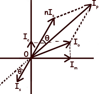
The above diagram represents the phasor (vector) diagram of a Current Transformer (CT) under operating conditions. The diagram contains several important current components
- Ip → Primary current (actual)
- Is → Secondary current (actual)
- n Is → Secondary current scaled to primary side (ideal)
- Ic → Core loss component of excitation current
- Im → Magnetizing component of excitation current
- Io → Total excitation (no-load) current
Io = Im + Ic - θ → Phase angle error of the CT
Let’s break down why CT errors occur and how the diagram shows them.
The actual transformation ratio of the CT \(\frac{I_p}{I_s}\) based on the above diagram. nIs is the ideal replica of secondary current referring to primary. However, the actual Ip is larger than n Is. This difference \(\frac{I_p}{I_s}\ – \frac{nI_s}{I_s}\) is because a part of the primary current does not get transformed to the secondary. Instead, a portion of the primary current is used to magnetize the core and overcome core losses. This portion is the excitation current (Io), which means the vector sum of Im and Ic. Obviously, the rated transformation ratio is \(n = \frac{nI_s}{I_s}\) , also based on the above diagram.
Ip = n Is + Io (vectorially). Obviously, this means the CT draws extra primary current to energize the core.
Ratio Error Formula
\[\text{Ratio Error} = \frac{I_p}{I_s} – \frac{nI_s}{I_s}\]
\[\Rightarrow \text{Ratio Error} = \frac{I_p – nI_s}{I_s}\]
You can also express it in a percentage.
\[\text{%Ratio Error} = \frac{(I_p – n I_s)}{ nI_s} \times 100\]
Understanding Phase Angle Error
A perfect CT requires Ip and Is to be exactly 180° apart. However in actual CT nIs and Is are exactly 180° apart. This is because, a small angle develops between nIs and Ip , due to excitation current Io
?This angle is θ, the phase angle error.
Saturation Error (Core Saturation)
When the CT core cannot carry any more flux, it saturates. This causes heavy distortion in the secondary current.
Why Saturation Happens
- High primary fault current produces more flux but after a certain flux it can not produce any more.
- DC offset during short-circuit also distorts the flux distribution and core may become saturated.
After saturation the core needs huge magnetizing current to increase the flux even slightly. Therefore the rate of change of flux linkage drops. As a result the secondary induced current becomes reduced and distorted. Therefore, CT under reports the actual fault current. In other word, protection relays may operate late or not operate at all.
Points to Remember
?Protection CTs must remain unsaturated during faults.
?Metering CTs must remain accurate at normal load.
Error Classes of Measuring CTs (IS 2705-2:1992)
| CT Class | Accuracy Purpose | Ratio Error Limit | Phase Displacement Limit | Typical Use |
|---|---|---|---|---|
| 0.1 | Very high precision | ±0.1% | ±5 minutes | Precision laboratory metering |
| 0.2 | High accuracy | ±0.2% | ±10 minutes | Energy meters, revenue metering |
| 0.5 | Standard accuracy | ±0.5% | ±20 minutes | General metering, panel meters |
| 1.0 | Moderate accuracy | ±1.0% | ±40 minutes | Indicating meters, ammeters |
| 3.0 | Low accuracy | ±3.0% | Not specified | Rough measurement, overload indication |
| 5.0 | Very low accuracy | ±5.0% | Not specified | Approximate load indication only |