When it comes to high-voltage power systems, current transformers (CTs) play a critical role. It has a vital role in measurement and protection. CTs come in two main designs—Live Tank and Dead Tank. While both serve the same fundamental purpose, they differ significantly in construction. Live tank and dead tank CTs differ mainly in insulation. Each type uses a different method to insulate the high-voltage components from the enclosure. This blog explains the key differences between Live Tank and Dead Tank CTs. It also shows their advantages and disadvantages. Finally, it helps you choose the one that suits your needs best.
What is a Live Tank Current Transformer?
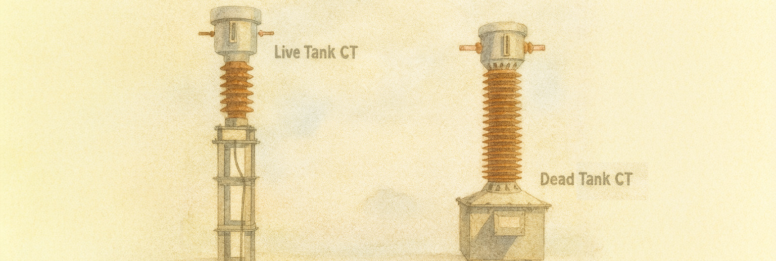
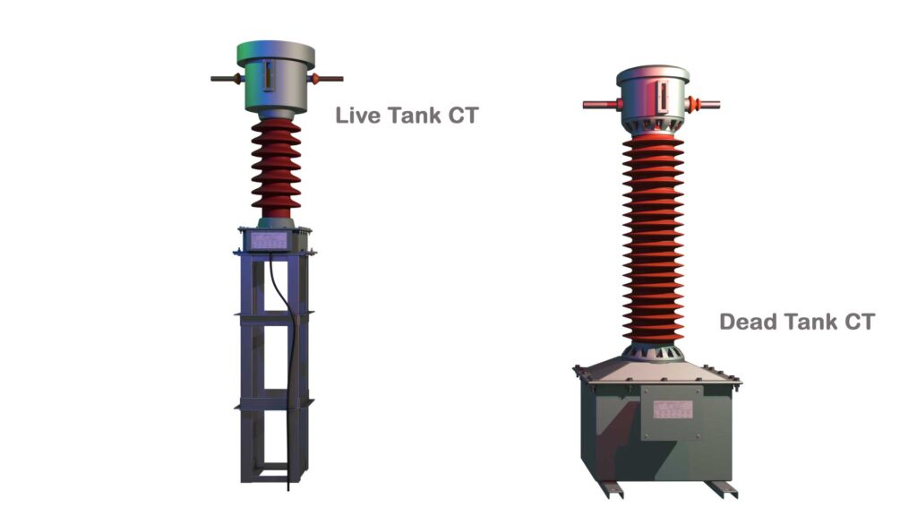
A Live Tank CT has its primary winding, core, and secondary winding inside a tank. This tank stays at system voltage, which means it remains at live potential. A porcelain or polymer insulator supports the entire structure and insulates it from the ground. The current transformer sits inside a metal tank. This tank connects directly to the live line through the CT’s primary terminals. Finally, the CT fits on top of the insulator column.
Key Features of Live Tank Current Transformers
- The primary winding, core, and secondary winding all remain at a high voltage level (live potential).
- The main mass of the CT lies at the top of the equipment. Hence, the CG stays in the upper portion of the equipment.
- An insulating cylinder supports the tank and insulates it from the ground.
- Typically smaller, lighter, and more compact compared to Dead Tank CTs.
- Engineers commonly use it at 132 kV and above because it offers cost and insulation advantages.
Advantages of Live Tank Current Transformers
Compact & Lightweight – The primary and the container stay at the same live potential. Because of this, a Live Tank CT needs less insulation material. It uses less paper, oil, or SF6 gas compared to a Dead Tank CT. It also makes the CT more space-efficient.
Better Cooling & Heat Dissipation – The primary winding usually uses a copper or aluminum rod. Sometimes it uses a few turns of copper or aluminum strip. Manufacturers generally do not cover it with insulation paper. Hence, it is in direct contact with insulating oil or SF6 gas, which improves heat dissipation.
Lower Magnetic Leakage – The core is smaller and efficiently surrounds the primary rod (winding), leading to better magnetic coupling. As a result, this design reduces flux leakage. Consequently, it ensures that the CT uses a greater portion of the magnetic field effectively.
Cost-Effective for High Voltage – As already mentioned, the primary and the container are in the same live potential, hence it requires less insulation material, reducing costs for 132 kV and higher rated current transformers.
Easy to design for short-circuit current – As the primary is a straight bar only, it is easier to design for higher short-circuit withstand capacity.
Faster Response to Transients – Due to better flux linkage, a live tank CT provides better transient performance in fault conditions.
Disadvantages of Live Tank Current Transformers
Maintenance Complexity – Since the entire tank is at high voltage, working near or on a live tank CT requires a total shutdown. Accidental contact with the tank is hazardous. Some designs restrict accessibility. The high-voltage tank sits elevated on insulators, which makes access more difficult.
Less Mechanical Stability – An insulator supports the entire high-voltage tank assembly. This design plays a critical role in mechanical stability. Raising the heavy tank on the insulator column creates a higher center of gravity than in dead tank CTs.
A live tank CT can become more susceptible to overturning moments. Seismic or wind forces increase this risk. The tank and insulator assembly act like a cantilever beam. Forces applied at the top create bending moments at the base of the insulators and the supporting structure. Severe short circuits can also cause mechanical movement of the tank and its components due to electromagnetic forces. Designers must consider these effects in the CT design.
Higher Insulation Stress – The top head, meaning tank, is at live line potential, and the base is at ground potential, and there is an insulator support in between. So this support insulator requires high-quality insulation coordination to prevent flashover. It may make the CT taller compared to a dead tank CT of the same rating.
What is a Dead Tank Current Transformer?
A Dead Tank CT houses the core, secondary winding, and part of the primary winding inside a grounded metal tank. Only the primary conductor inside the tank is at high voltage, making the exterior safer and easier to maintain.
Key Features of Dead Tank Current Transformers
- The primary winding loop extends down to a grounded metal tank. The grounded tank encloses the cores and the secondary windings.
- The entire tank is at ground potential. The secondary terminals are connected to the secondary studs fixed on the tank. This makes the maintenance and other work on the secondary terminals side easier without requiring a shutdown.
- The primary winding requires thick insulation since it must withstand the voltage stress between the live winding and the grounded metal tank. As a result, these CTs become larger and bulkier due to the need for thicker insulation.
- Engineers commonly use them in 33 kV systems. In such systems, the size and cost of insulation matter less.
Advantages of Dead Tank Current Transformers
Safer for Maintenance – Since the tank is grounded, technicians can safely inspect, work, and maintain the CT secondary terminal side without de-energizing a dead tank current transformer.
Better Mechanical Stability – As the main mass lies at the bottom of the CT structure, it is mechanically more stable to wind pressure and other cantilever forces.
Better Protection Against External Magnetic Field – The grounded tank shields the CT from the external magnetic field.
Lower External Insulation Requirements – No need for complex insulation coordination as the tank is at ground potential.
More Stable in Polluted Environments – Works better in areas with high pollution, salt deposits, or extreme weather conditions.
Disadvantages of Dead Tank Current Transformers
Bulky & Heavy – Requires more insulation material, making it larger and harder to install.
Higher Core Saturation Risk – In a dead tank CT, the primary conductor enters and exits the grounded metal tank, creating an asymmetric magnetic circuit around the core. Unlike Live Tank CTs, where the core is evenly distributed around the primary conductor, the magnetic flux in Dead Tank CTs is non-uniform due to the off-center primary conductor placement. Unequal flux distribution leads to higher core saturation in certain regions, affecting the accuracy of secondary current measurement.
Higher Cost for High Voltage – More insulation material means increased costs for 132 kV and above applications.
Slower Transient Response – As the primary winding is longer, it offers more reactance. More reactance means this CT takes longer to respond to sudden changes in current.
Susceptible to Partial Discharge – In a dead tank CT, the primary winding is insulated from the earthed tank, which can be more challenging to achieve than in a live tank CT, where the primary winding is at the same voltage level as the tank. This can make the insulation in a dead tank CT more susceptible to partial discharge. Also, the primary winding in a dead tank CT is longer and has to pass through the porcelain or polymer insulator cylinder, which can make it more vulnerable to mechanical stress during short circuits.
This can damage the insulation and increase the risk of partial discharge. The primary winding in a dead tank CT has a larger volume of copper, which can lead to more heat generation during short circuits. This can make it more difficult to dissipate the heat, and the trapped heat can degrade the insulation. It can also contribute to partial discharge. Overall, dead tank CTs can be more susceptible to partial discharge.