Not only a power transformer, but all transformers have only two main parts. These are the windings and the core. All other parts associated with the transformer are just there to support the working of the transformer. Actually, the principle of a transformer is based on these two elements — the winding and the transformer core.
In this article, we will focus on the core. Our discussion will include the purpose of the transformer core, the types of transformer cores, and the design of transformer cores with different materials used for the core.
Purpose of Transformer Core
A transformer transfers alternating electrical energy from one circuit to another without any direct electrical connection. It works on the principle of mutual inductance between two windings. Mutual inductance depends upon the flux linkage between the primary and secondary windings. Obviously, a transformer core ensures maximum flux linkage between the primary and secondary windings. In other words, the core reduces leakage flux as much as possible in a transformer.
Definition of Transformer Core
A transformer core is a low-reluctance magnetic path. This closed magnetic path links the primary and secondary windings to ensure maximum flux linkage and minimum flux leakage between the windings.
Material Used – Basic Structure
Although the magnetic core of a transformer provides a low-reluctance, high-permeability path for magnetic flux to pass through, it has its own drawbacks. It suffers from two kinds of losses, eddy current loss and hysteresis loss.
Needs Laminations
To minimize these losses, manufacturers use a laminated core. They use several thin sheets of ferromagnetic material, each insulated from the others and assembled to form the entire structure of the core. Ferromagnetic materials like silicon steel offer a low-reluctance path for the flux. The varnish or oxide coating on the laminations provides resistance to the eddy current path. The resistance due to insulation coatings reduces the eddy current. Therefore, the eddy current loss in the transformer decreases. Because the eddy current loss is directly proportional to the square of the eddy current.
Needs of CRGO
On the other hand, manufacturers use cold-rolled grain-oriented (CRGO) silicon steel to produce the laminated steel sheets. Cold-rolled grain orientation reduces hysteresis loss in the core because the grains of the iron crystals are already oriented, resulting in less randomization. As a result, hysteresis loss is reduced.
The typical silicon content of CRGO is about 2 to 4%. Sometimes, some special steel may contain up to 7% silicon. The presence of silicon in the silicon steel greatly increases the resistivity and lowers the hysteresis loss. Also, ultra-low carbon steel is used to achieve maximum efficiency. Normally, the thickness of each lamination is about 0.23 mm to 0.27 mm.
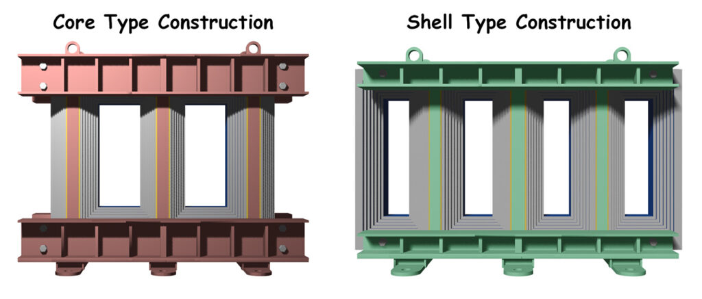
Types of Transformer Core
There are two types of transformer cores we normally use. The most popular type is the core-type transformer core construction, followed by the shell-type transformer core. In the core-type design, we place the primary and secondary windings on the limb of the core. For a single-phase transformer, we place both primary and secondary windings on both limbs.
In shell-type core construction, there is a minimum of three limbs in a core. The central limb holds both the primary and secondary windings. That means the core surrounds the winding. In contrast, in core-type construction, the windings surround the limb of the core.
Three-Phase Core Construction
The three-phase core-type construction has three limbs of equal cross-section. Each limb holds both the primary and secondary windings of one phase of a three-phase system. However, in a shell-type structure, there is a minimum of five limbs in the basic construction of the core. The central three limbs hold the red, yellow, and blue phase windings, respectively. The outer two limbs provide a closed return path for the magnetic flux.
In core-type construction, we generally use concentric winding. We place the LV winding first on the core. Then, above the LV winding, we place the HV winding. This arrangement optimizes the insulation.
In shell-type transformers, we generally use sandwiched winding. We divide both HV and LV windings into several winding discs. We place them alternately on the limb of the transformer. The first and last winding discs will be LV. It makes the isolation arrangement optimized.
Amorphous Core and Nanocrystalline Core
We also use some other materials for the construction of transformer cores. The main variants of these modern materials are amorphous core and nanocrystalline core materials.
Many manufacturers nowadays use amorphous cores for distribution transformers. It significantly reduces the core loss of the transformers. But as amorphous metal is quite fragile, we cannot construct and handle easily a larger lamination sheet with amorphous metal. Therefore, this problem limits the use of amorphous cores for larger power transformers.
In current transformers and potential transformers, many manufacturers nowadays use nanocrystalline cores. Nanocrystalline cores require a much smaller magnetizing component of the primary current. Thereby, they significantly reduce the error in an instrument transformer.
Difference between Core Type and Shell Type Cores
Shell-type transformer cores have several advantages over core-type. Core-type constructions also offer some benefits.
Advantages of Core Type
The winding arrangement in a core-type transformer is quite simple. First, we place the entire LV winding on the core. Then, we place the HV winding above the LV winding. This also includes the tap-changing winding. This winding arrangement improves cooling. The insulation arrangement is simple too. This design is economical.
Manufacturers commonly use this type of core. Core-type construction is lighter and smaller than shell-type cores.
Advantages of Sheel Type
Now, let’s look at the advantages of shell-type transformers. In shell-type transformers, we divide the LV and HV windings into several discs. We place these discs alternately on the core limb. This arrangement is called the sandwich-type design.
The sandwich design increases the mechanical strength of the windings. Hence, it helps the transformer to withstand short-circuit currents more effectively. This winding layout also reduces flux leakage. The ferromagnetic core surrounds the windings. So, this improves electromagnetic shielding.
Another key benefit of the shell-type core is better flux confinement. It contains the magnetic flux more efficiently than core-type designs. Its enclosed structure also reduces noise and humming.
Shell-type transformers offer a big advantage in terms of height. Manufacturers often need to limit transformer height due to transportation rules. They must ensure the unit fits on trucks or trains without violating height limits. In such cases, manufacturers prefer shell-type cores. Shell-type cores are shorter than equivalent core-type designs. This lower height reduces the overall height of the transformer. It makes the transformer easier to transport smoothly and safely.