For Battery Sizing Calculation
First, we consider a single battery bank for DC power for the entire substation. In our case, the DC system is 220V; hence, we first set the voltage rating of our battery to 220V.
Here, we need to note for future extension of the substation. Because once we installed the battery bank, it is not practical and economical to replace the battery bank with a higher-rated battery, when the DC load will increase due to future extension of the system of the substation. Therefore, we shall consider the forecasted future bays now at this initial stage.
Considering the Conditions for Battery Sizing Calculation
Now, we shall consider two extreme conditions when the battery will supply the maximum DC load.
Initial Peak Load Situation
- Suppose there is a bus differential protection or LBB protection operating. At that instant, the circuit breaker of all the feeders will trip at the same instant. Here, in our example, it is a 220/33KV substation. The bus differential and LBB are associated only with the 220 kV bus. So, 220KV feeders will trip instantly during bus differential protection or LBB protection actuation. So, here we do not need to consider the 33Kv feeders.
- After the bus differential or LBB operation, the entire substation comes under blackout. In other words, there is no AC power available in the substation. This is because, under these conditions, 33KV shall not get any power. The auxiliary transformer obtains power from the 33KV system only. However, there are many DC loads that run continuously during the blackout condition.
Continuous DC Load
- Most commonly, manufacturers design a battery bank with \(C_{10}\) capacity. Meaning, it can deliver quality DC power at a specified voltage level for at least 10 hours. That means the battery can deliver the rated current to the load while maintaining the minimum specified voltage limit for a continuous 10 hours. Therefore, we will consider the extreme condition where the blackout lasts for 10 hours. During this time, the relay will draw its required continuous DC power. The Station Automation System (SAS) will also consume its required DC power. Also, all IEDs and indicating lamps, which remain continuously glowing, will take DC power. Some miscellaneous systems also draw DC power from the battery, such as the firefighting system and ACDB.
- In the extreme case, the blackout may occur at night. During this time, all emergency DC lights will glow. Hence, we must consider that all lights remain glowing throughout the blackout period. Suppose the battery needs to supply this continuous load for the maximum time limit of 10 hours after bus differential protection operates.
Final Peak DC Load
- After that, we will re-establish the AC power system by closing one of the 220 kV feeder breakers. If the breaker has a spring-charging mechanism with a DC motor, the motor will also consume DC power during the closing operation of the breaker.
- Next, we must close the 220 kV side of a transformer to energize a 220/33 kV transformer and re-establish supply to the 33 kV system. If, during the blackout, the operator has manually switched off the 33 kV system, then the 33 kV breaker must also be closed. In such an extreme condition, the spring-charging motor of the 33 kV breaker will also consume DC power. Here, we have considered that the 33KV CBs also have a DC spring charging motor.
- This means all these are DC loads. Finally, we need to close the 33 kV breaker associated with the station transformer to energize the AC distribution board. Once the AC supply is restored, the charger will be switched on, and the battery charging will resume.
Considering the Minimum Marginal Discharged Voltage of Battery Cells
So, we must figure out the required DC load to establish AC power after the maximum prolonged blackout.
During this time, the battery must be able to deliver DC power without dropping below its specified voltage level. Normally, as per standards, the voltage of each lead-acid VRLA battery cell is 2 volts. The minimum safe limit is 1.75 volts per cell. However, it is good practice to consider 1.85 volts as the lower limit. In our case, we will adopt 1.85 volts as the safeguard. This means that after 10 hours of discharging, the voltage of each cell should remain above 1.85 volts.
Considering Durations of the Loads
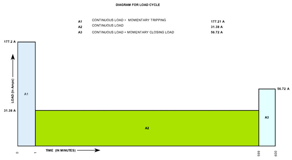
Next, we consider the momentary ampere load during differential tripping of all the 220kV circuit breakers. Although the actual tripping occurs within a millisecond range, for battery sizing calculations, we assume a duration of 1 minute (0–1 minute). This is the standard practice.
After that, there will be a continuous load, as we have discussed. For this, we must calculate the ampere loading of the battery for the full 10-hour period (0–600 minutes).
At the last minute of this period, we also need to account for the operation of the circuit breaker required to re-establish AC power.
Hence, we must calculate the battery’s ampere loading considering both the momentary and continuous loads.
Considering K-Factors
Now, we come to the concept of the K-factor. The K-factor is a value that defines the ampere-hour rating of a battery for a given current over a specified time. In other words, it indicates what ampere-hour capacity the battery must have for a certain discharge current and duration. Manufacturers provide K-factor tables, and using these, we can calculate the required ampere-hour rating.
Load Cycle Diagram for Battery Sizing Calculation
Section – 1: The first section of this calculation is the initial 0–1 minute, during which all the 220KV circuit breakers trip due to bus differential protection. From this, we estimate the ampere-hour requirement. Then we proceed to calculate the subsequent continuous load.
Section – 2: The battery bank must support continuous operation from 1 minute to 599 minutes, considering the ampere load during that period.
Section – 3: In the final section, when we re-establish AC power, we must calculate the ampere-hour requirement of the battery based on the current loading at that time using the K-factor.
From this, we perform another calculation to determine the actual ampere-hour requirement of the battery during each of these periods. After comparing all three sections, the maximum ampere-hour rating obtained will be considered for our purpose.
Additional Factors to be Considered for Battery Sizing Calculation
In addition to this, we need to apply other factors:
- Design Margin – A margin is added as per the agreement between the manufacturer and purchaser. Commonly, this factor is taken as 1.05.
- Aging Factor – When the battery is newly installed, its capacity and performance are satisfactory. However, after years of operation, the performance deteriorates. The battery must still deliver the required capacity even after 20 years of service. Therefore, the initially installed capacity must be higher than the calculated value. This ensures that even after aging, the battery can still provide 100% of the required capacity. The commonly used aging factor is 1.25.
- Future Load Growth (Spare Capacity) – As per the customer agreement, the manufacturer must also provide some spare capacity. This allows the battery to handle additional load if the current demand increases beyond the forecasted requirement. The commonly used factor for this is 1.20.
Battery Sizing Calculation for First Section
After calculating the current loading of the first section (0–1 minute), during which all the 220 kV circuit breakers trip simultaneously, we also need to account for the continuous load during this period. Since it is continuous, this current loading must also be added. From the K-factor table, we will find the exact K-factor corresponding to that ampere load and time duration. By multiplying the current loading by the K-factor, we can obtain the ampere-hour requirement for this section.
Battery Sizing Calculation for Next Section
Next, we move to the second section. Here, we check whether the continuous load is less than the initial peak load. If so, we must consider the change in ampere loading just after the first minute. For calculation purposes, we assume the peak load also continues from 1 to 599 minutes, i.e., 598 minutes. Here, the actual continuous load runs from 1 to 599 minutes (598 minutes) during this section.
We then calculate the ampere-hour loading considering both the peak load and the change in ampere loading during the continuous load condition. Using the K-factor list, we determine the exact K-factor, multiply it by the ampere loading, and obtain the ampere-hour requirement. The difference in ampere-hour loading will give the actual ampere-hour capacity of the battery for this section.
Battery Sizing Calculation for Third Section
In the third section, we consider all three stages:
- the first section (peak section),
- the second section (continuous section), and
- the final one-minute section during power restoration.
For this final stage, we determine the ampere-hour loading by calculating the change in load and applying the appropriate K-factor. Finally, we add up the ampere-hour requirements of all three conditions.
Maximum Battery Size
We shall take the maximum ampere-hour value obtained from these three sections as the basic ampere-hour rating of the battery.