A power transformer has high cost, large size, and complex design. So, identifying defects at the final stage of manufacturing can lead to significant delays, expenses, and operational challenges. Therefore, standards always recommend performing different tests and inspections during various stages of manufacturing. That means the standards always prefer to perform stage inspections of a power transformer during different stages of manufacturing. This article explains why stage inspection is important. Also, it focuses on the guidelines provided by standards like CBIP for performing these inspections effectively.
Key Stage for Inspection of a Power Transformer
One major stage is just after the manufacturer completes the construction of the tank, core, and windings of the transformer. If there are any defects in these parts, it would be unnecessary for the manufacturer to assemble the transformer or proceed further with the manufacturing process before rectifying the issues. This is the reason CBIP in India and other relevant standards recommend performing a stage inspection of a transformer after completing the core assembly, windings, and tank of the transformer.
Stage Inspection of a Transformer Tank
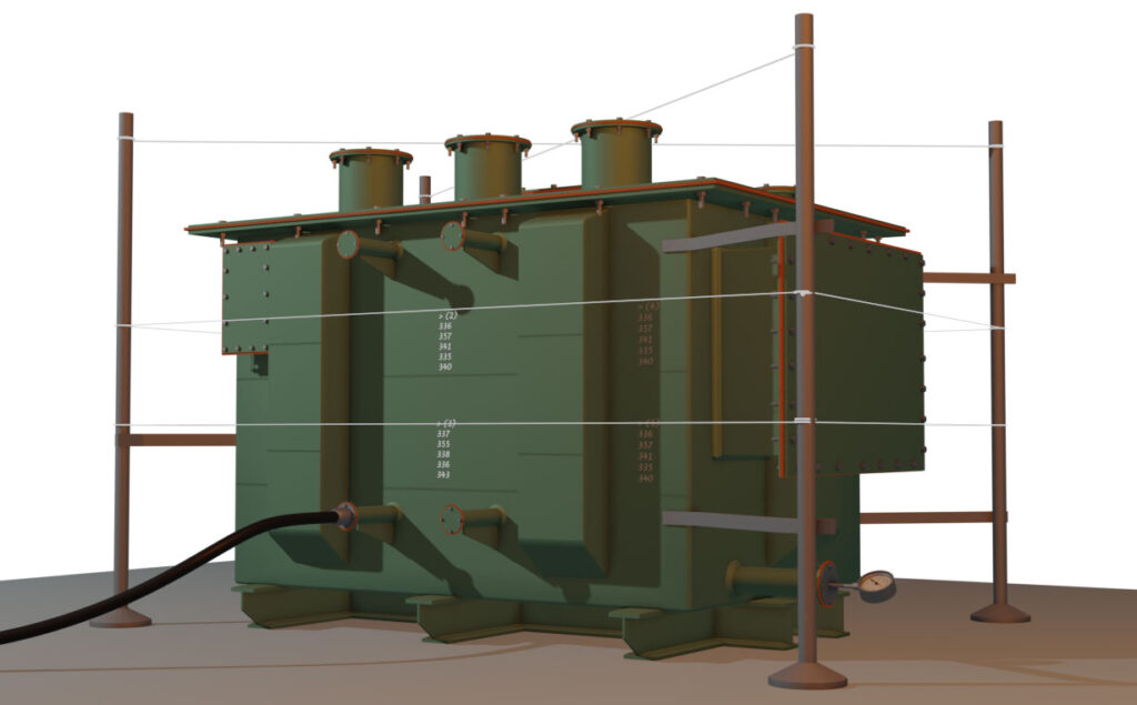
The manufacturer places the empty tank on the stage test bed. They place four poles at least at the four corners of the tank. Also, they can weld at a few different points on the tank with the strip to the pole. This helps the pole to stand fixed and stationary with respect to the tank.
Then they block all the openings of the main tank with gaskets and blanking plates. That means they block the radiator openings, conservator openings, and diverter tank openings by dummy plates or blanking plates. Now they fit a pressure gauge with the flange on any of the openings. Normally, they fit the pressure gauge at the lowest point of the tank, that is, through the opening of the drain valve of the tank.
Now they fit a vacuum pump of sufficient capacity to any of the openings. After that, they use threads from one pole to another and tie them very tightly so that the threads remain straight. Also, they do the same at the top of the tank.
Marking and Measuring
Now they put marks on the tank body at different locations aligned with the running straight threads. Now, they measure the perpendicular distance between the mark and the thread. They record the readings for future reference. They mark those points where there is a chance of maximum deflection during vacuum or pressure in the tank. After taking all the readings and writing them beside the marking on the tank body, they start the vacuum pump.
Recommended Vacuum Pressure
The CBIP manual does not recommend going for a full vacuum inside the tank. Rather, it suggests going up to 25 torr pressure inside the tank. That means during this stage, inspection of a transformer, the vacuum pressure inside the tank should remain at 25 torr. So they first check the atmospheric pressure at that location and then subtract 25 torr from it. This subtracted value is in millimeters of mercury column. They will finally stop the vacuum pump when the vacuum pressure gauge shows that reading.
Suppose the atmospheric pressure of that place is 742 mm of mercury column. So, they need to keep the vacuum pressure inside the tank at 742 – 25 = 717 mm height of mercury column.
Also, the CBIP manual recommends not to go for full vacuum pressure for the tank of the transformer below 20 MVA. If it is under 20 MVA, then they may apply 500 – 25, that is, 475 mm of mercury column instead of standard vacuum pressure.
Process of Vacuum Test of Transformer Tanks
Now, they must keep the vacuum for one hour. Then they release the vacuum and take the final measurement in the same process. If the perpendicular distance from the thread to that mark changes and it is beyond the limit recommended by the CBIP standard, then the test fails. Therefore purchaser can reject the tank.
Pressure Test of Transformer Tanks
After that, they will go for the pressure test of the transformer tank.
Recommended Pressure
How much pressure to be applied in the tank is also recommended by the CBIP manual. We need to calculate the oil head when the transformer is filled with oil, and then just multiply it by 2. Whatever pressure we get, we have to apply that pressure inside the tank for one hour. Otherwise, we have to apply normal pressure plus 35 kilo Newton per square meter. The CBIP manual recommends applying whichever is lower of these two calculations.
Process of Pressure Test of Transformer Tanks
After reaching that pressure, we stop the pressure pump. Then we wait for one hour. After that, we release the pressure and take the measurement again. If the differences between initial and final readings are still within the range recommended by the CBIP manual, the test passes. Otherwise, the test fails.
Stage Inspection of a Transformer Core
Core Loss Measurement
We wrap the limbs of the core with insulated cable and apply voltage according to the per-turn voltage of the transformer. The number of turns should not be too large, as this will require excessive voltage supply due to the core loss wattage. At the same time, the number of turns should not be too few because too few turns cause a very high current to flow. To limit the current, we need to increase the number of turns to an optimized number. Therefore, instead of providing only one or two turns, we generally provide seven to eight turns for better performance.
\[\text{Low voltage rating } V_{L} = 11\text{ kV } = 11,000\text{ V } \]\[\text{ Number of turns in LV } N_{L} = 149\]\[\text{Voltage per Turn }V_T = \frac{V_{L}}{N_{L}\times \sqrt{3}}\]\[\text{ Since, we have considered the LV is star connected}\]\[V_T = \frac{11000}{149\times \sqrt{3}}\]\[V_T = 42.62 \text{ V }\]\[\text{Applied supply voltage }V_T\times 7 = 42.62\times 7 = 298.37 \text{ V per phase}\]\[\text{Because, we have wrapped the cable 7 times on each limb of the core}\]
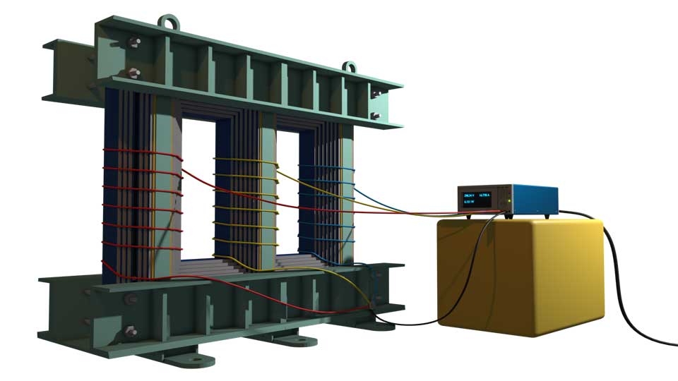
Then, we need to verify the measured value displayed on the screen of the measuring instrument against the guaranteed loss provided by the manufacturer. If it is below the guaranteed loss, we accept the test.
Physical Verification of the core during Stage Inspection
Now we go for visual checking of the overall finishing of the core. Here, we measure different parameters like thickness of the core laminations, window height, leg center to leg center distances, overall height of the core, number of steps, core diameter, stack thickness, width of the step, etc. Then we record these readings and tally them with the guaranteed design value. We also do physical verification, like age, finish, cutting, sharpness, and tightness of the lamination.
Then we take a sample of lamination as cut pieces from the core to send it to a third-party laboratory for testing purposes. This is for verifying the guaranteed CRGO material of the core.
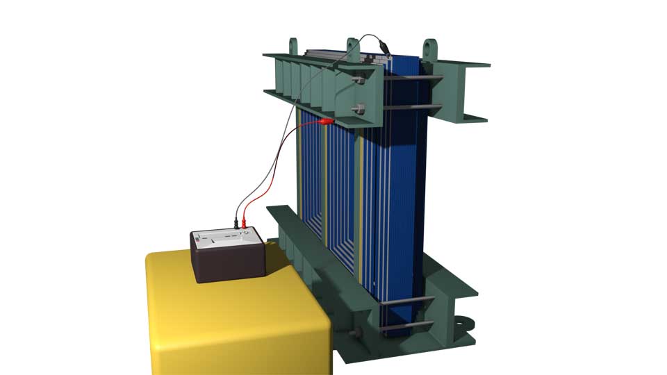
Core Isolation Test
Then we go to the core isolation test of the transformer. In that case. This is also an important test performed during the Stage Inspection of a Transformer. Here we use an IR measuring instrument of likely 2.5 KV rating. Then we connect the 2 leads of the meager one with the clamp, and another with the core. Then, we measure whether any sorting exists between the core and the metal clamp. If the IR measuring instrument shows a sufficient IR value in the giga-ohm range, we can conclude that there is no shorting between the core and the clamp.
Stage Inspection of a Transformer Winding
Here we will perform two major measurements. One is dimensional checking, and the other is the ohmic resistance measurement of the low-voltage (LV), high-voltage (HV), and tap-changing windings. For measurement purposes, we will measure the thickness and width of the conductor strips along with the paper insulation, as well as the bare part of the copper conductors.
We will also count the number of discs in each winding. Additionally, we will verify the parallel conductors for each turn and compare them with the design. We will also measure the height of the winding. One major parameter is the inner and outer diameter of the winding. Suppose now, we are measuring the LV winding. Since it will be placed on the limb of the transformer core. So, we must measure the inner diameter of the LV winding and compare it with the measured diameter of the core.
Then we will check whether this LV winding fits correctly on the core. After that, we will repeat the same measurement for the HV and tap-changer windings. We will carefully measure the inner diameter of each winding to verify whether:
- The HV winding fits properly on the LV winding, and
- The tap-changer winding fits properly on the HV winding.
So, inner diameter measurement and examination are essential.
Measurement of Winding Resistance
For measuring the winding resistance, we will use the voltage drop method. We inject, say, 10 amperes into the winding by connecting the current terminals of the measuring instrument to the beginning and end terminals of the winding. We also connect the potential terminals close to the current terminals to measure the voltage drop caused by the injected 10-ampere current.

From this injected current and the measured voltage drop, the instrument calculates and directly displays the DC resistance value of the winding. Similarly, we will perform the same procedure for the HV winding. However, as the current rating of the HV winding is lower and the number of turns is greater than in the LV winding, we will use 5 amperes in that case. We shall repeat the measurement of the tap changing windings by connecting all the tap ends in series.