
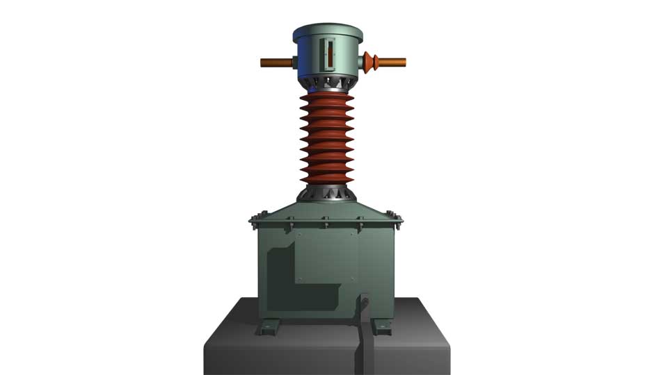
In this article, we are going to discuss the dead tank CT or dead tank current transformer, commonly referred to as a dead tank CT.
Dead tank current transformers are not popular for very high-voltage systems like 220 kV and above. Utilities often use dead tank CTs in 33 kV systems. They prefer this design at 33 kV because manufacturing a dead tank CT for very high voltage systems like 220 kV and above is not economical. However, due to its mechanical stability, many utilities use dead tank CTs in 33 kV systems. This is because, the center of gravity in a dead tank current transformer lies at the bottom. This makes it mechanically more stable compared to a similarly rated live tank current transformer.
Why do we call this CT a dead tank CT?
In a dead tank current transformer, the entire current transformer assembly is located at the bottom. Obviously, here, the entire assembly includes the primary and secondary windings. The tank covering this portion remains at dead potential. The grounding system of the substation directly connects to the tank.
Construction of a Dead Tank CT
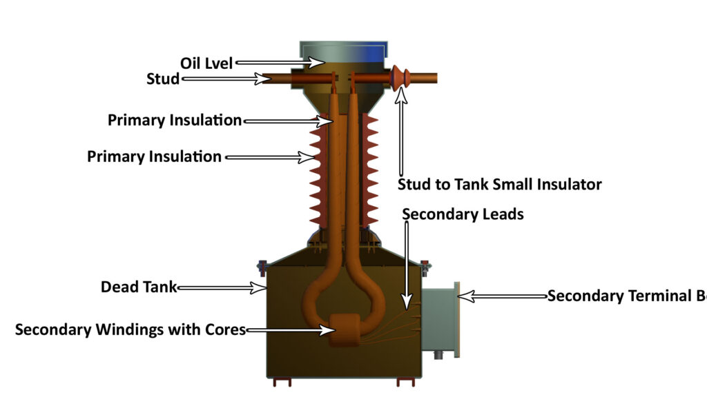
Primary and Secondary Windings and Cores
Like a live tank current transformer, it has a primary lead at the level of the power line. From this point, the primary loop runs downward. The primary loop is nothing but a thick copper or aluminum conductor.
The primary lead is insulated with electrical-grade paper insulation. This insulation must be thick enough to withstand the voltage difference between the live conductor and the grounded tank at the bottom.
Next, the manufacturer places the CT cores side by side on the primary loop. The manufacturer uses a smaller cross-sectional core for metering purposes, whereas it uses a larger cross-sectional core for protection purposes.
The manufacturer wraps the cores with electrical-grade insulation paper. Then, it winds enamel-coated or paper-insulated thin wires over them to form the secondary winding. The secondary winding wire is usually a single strand. Since the current in the secondary is about one ampere. So the secondary wire diameter is small.
Dead Tank
The secondary leads come out from the winding ends and connect to the secondary terminal box. This box contains all the terminals side by side and has a removable door cover. At the bottom of the box, there is one or two cable glands to allow entry of the external secondary connection cables.
The manufacturer mounts the secondary terminal box on the bottom tank, which is the dead tank. This dead tank supports the insulator housing on top. On top of the insulator housing, there is a smaller header tank. This top metal tank holds the primary lead in position.
The manufacturer places insulating material between the top tank and the primary lead. This ensures proper insulation, similar to a live tank current transformer.
Manufacturers also provide a pressure relief valve at the top of the transformer. Additionally, they provide an oil level indicator on the top tank to check the oil level inside.
The oil level should always keep the connection between the primary loop and the top terminal submerged. There must also be sufficient space above the oil for breathing purposes. When the oil expands due to heating from the operating current transformer, the header tank accommodates the expansion.
Finally, manufacturers cover the header tank to give the transformer a more aesthetically pleasing appearance.