What is Normal Current Rating?
This is the current represented in its RMS value. Electrical equipment can carry this current continuously without being overheated and without losing its desired performance. According to IC 62271, the definition of normal current rating of electrical equipment is the rated normal rms current that the electrical equipment can carry continuously under specified conditions of use and behavior.

R10 Series for Current Ratings
Different utilities and customers require different current ratings for their equipment. They can determine the normal current-carrying capability of electrical equipment based on their load demand. However, manufacturers do not find it economical to produce equipment tailored to various customer-specific current-carrying capacities. It is neither economical nor practical from the manufacturing point of view. Moreover, such highly requirement-specific current-rated electrical equipment can create confusion even at the consumer end.
To avoid this type of difficulty, manufacturers use the R10 series to fix the current rating of commercially available electrical equipment in the market. The R10 series comprises the numbers 1, 1.25, 1.6, 2, 2.5, 3.15, 4, 5, 6.3, 8, and 10, and their products by \(10^{n}\), where n is 1, 2, 3, etc.
| Index (n) | Expression (10n/10) | Calculated Value | Approx. Value |
|---|---|---|---|
| 1 | 101/10 | 1.259 | 1.25 |
| 2 | 102/10 | 1.585 | 1.60 |
| 3 | 103/10 | 1.995 | 2.00 |
| 4 | 104/10 | 2.512 | 2.50 |
| 5 | 105/10 | 3.162 | 3.15 |
| 6 | 106/10 | 3.981 | 4.00 |
| 7 | 107/10 | 5.012 | 5.00 |
| 8 | 108/10 | 6.310 | 6.30 |
| 9 | 109/10 | 7.943 | 8.00 |
| 10 | 1010/10 | 10.000 | 10.0 |
Normal current ratings of high voltage electrical equipment are 1000 A, 1250 A, 1600 A, 2000 A, 2500 A, 3150 A, 4000 A, 5000 A, 6300 A etc. Also, short circuit current ratings of electrical equipment are either of 16 kA, 20 kA, 25 kA, 31.5 kA, 40 kA, 50 kA, 63 kA, 80 kA, 100 kA.
Temperature Rise limits for Normal Current Ratings
The normal current rating depends on the temperature rise of the equipment while carrying the rated normal current continuously. The continuous current generates heat. The equipment must have a sufficient heat dissipation arrangement to balance it. When the equipment carries the rated normal current, the temperature should remain within the range given by the standards.
IS 62271:2007 or IEC 62271:2007 standard lists which parts of the equipment like high-voltage switchgear and control gear can withstand specific temperatures.
Temperature Rise Limit for Conductive Parts
For bare copper or for bare copper alloy current-carrying part of a switchgear:
- If it is in air, the maximum allowed temperature is 75°C
- In SF6 gas environment, it can withstand 105°C
- In oil, it is 80°C
For silver-coated nickel copper:
- In air it will be 105°C
- Also in SF6 it is 105°C
- and in oil it is 90°C
If the copper is tin-coated then it will be 90°C irrespective of air, SF₆ and oil.
Temperature Rise Limit for Insulation Parts
Also, the insulation used in the switchgear will also have some temperature rise limit and that must also be considered for designing the switchgear. If the insulation is Y type insulation then the temperature rise limit should be 90°C. When it is A type, it will be 105°C. If it is E type then it will be 120°C. For B type it is 130°C, for F type it is 155°C. If it is enamel, meaning oil-based synthetic, then it will be 100°C and if it is H type then it will be 180°C.
| Insulation Type | Temperature Rise Limit (°C) |
|---|---|
| Y Type | 90°C |
| A Type | 105°C |
| E Type | 120°C |
| B Type | 130°C |
| F Type | 155°C |
| Enamel (Oil-based Synthetic) | 100°C |
| H Type | 180°C |
Note that the current-carrying part in a vacuum environment does not follow the temperature rise limit. This means temperature rise limits do not apply in a vacuum. However, the remaining parts of the equipment must follow the temperature rise limits.
For cables, choose the temperature rise limit so that it does not cause damage or permanent deformation to the surrounding insulation material.
When electrical equipment contains different parts—some coated with silver or tin and others left bare—you must consider the temperature rise limit of the bare conductor to ensure the equipment stays within its overall temperature rise limit.
Temperature Rise Test
To ensure the temperature rise limit while the electrical equipment carries the rated maximum normal current, engineers must conduct a temperature rise test as a type test on the equipment.
Conditions for Testing
Engineers must conduct the temperature rise test in an indoor environment without wind or air currents. Otherwise, the heat generated by the equipment will sweep away from the device being tested. As per standard practice, the air velocity around the testing equipment should not exceed 0.5 meter per second.
Equipment Setup
When we conduct a temperature rise test on electrical equipment, we assemble it completely with all its auxiliary arrangements. We must also fit all covers and extra covers on the equipment. This setup isolates the equipment from any external heating or cooling. It means the equipment should be fully covered as it would be when in the actual service condition.
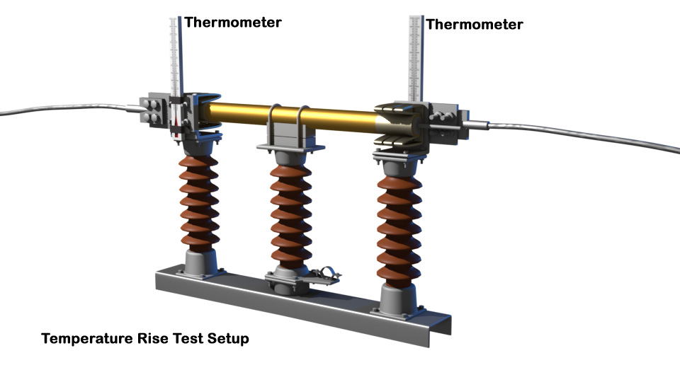
We place the temperature sensors, such as thermometers or thermocouples, at the current terminals of the equipment and also at a distance of one meter from the temporary connections. After that inject current at a frequency of 50 Hz during the temperature rise test, with a specified tolerance.
Duration and Readings of Temperature Rise Test
We must perform the test over a period long enough for the temperature rise to reach a stable value. Until the temperature stabilizes, we must continue injecting the rated maximum normal current into the equipment. We take temperature readings from all sensors at one-hour intervals. When the temperature rise does not exceed \(1^o\) in consecutive recordings taken at one-hour intervals, we can consider the temperature to have stabilized.
We may shorten the total test time by preheating the circuit using a higher current during the temperature rise test. We must also record the ambient temperature throughout the entire testing period. Temperature sensors or detecting devices (thermometers or thermocouples) used for measuring the ambient temperature must be evenly distributed around the switchgear. We must use at least three such devices and place them equally at appropriate locations, about one meter away from the equipment under test. The height of each temperature sensor should be approximately equal to the height of the current-carrying part of the equipment.