Location of Capacitor Banks
It is always desirable to connect a capacitor bank as close as possible to the load. This optimizes the use of the capacitor bank. Whenever we connect a load to the power system, the capacitor associated with that load also becomes connected to the system. The capacitor cancels out the reactive power caused by the inductive load.
However, there are a few difficulties. Firstly, it is not practical to connect a capacitor to each inductive load. It is also challenging to install appropriately rated capacitors for varying loads. Moreover, the system does not connect all inductive loads simultaneously. When we disconnect some loads, the capacitors associated with them remain unutilized. Obviously, this is not desirable from an economic point of view.
Centralized location of Capacitor Bank
A better, though not perfect, solution is to install a centralized, larger capacitor bank at a substation. A substation distributes the loads to various locations. This centralized approach is more manageable and cost-effective. Some medium-voltage or high-voltage consumers can install their own capacitor banks at their premises to compensate for their own inductive loads. However, even after such installations, significant inductive loads remain connected to the system. Examples of such connected inductive loads are power transformers, reactors, induction motors, and the network itself. Because the system itself has its own inherent inductive properties. Therefore, the system still needs a compensation of reactive power, even after the installation of capacitor banks at the consumer ends.

We must also note that not all reactive loads operate simultaneously. As a result, there is usually a continuous average reactive demand in the system. After estimating the average reactive demand, we calculate the required MVAR rating of the capacitor bank for installation at the substation. It is generally economical to install a large central capacitor bank at the transmission, sub-transmission, or distribution substation. It helps to improve the power factor, enhance voltage regulation, reduce ohmic losses, and increase the current-carrying capacity of the system.
Connection of Capacitor Banks
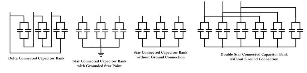
Generally, we use shunt capacitor banks in substations. We install these shunt capacitor banks normally in either star or delta configurations. Again, we can use a star-connected capacitor bank in either grounded or ungrounded configurations. We make a decision whether we install a grounded or ungrounded star-connected capacitor bank, depending on the protection scheme adopted for the bank.
There is also a special type of star-connected bank. We refer to it as a double-star-connected capacitor bank. Normally, we use star-connected shunt capacitor banks. The decision on whether we shall install a star-connected or delta-connected and grounded or ungrounded capacitor bank depends on three main factors.
The first is the MVAR rating, which means the size of the capacitor bank.
The second is the fault current level of the system to which the capacitor bank will be connected.
The third is the protection scheme of the capacitor bank.
Among all configurations, the grounded star-connected capacitor bank is the most popular. This is because this configuration helps to reduce the recovery voltage of the circuit breaker associated with the capacitor bank. It also provides better surge protection. Additionally, a grounded star configuration reduces overvoltage problems, and it is much easier to install.
However, the main drawback of a grounded star-connected capacitor bank is its susceptibility to zero-sequence current. The zero-sequence current affects this configuration significantly as it provides a clear path for such currents to flow.