What is the Rated Voltage Factor in voltage transformers, and how is it determined?
This is the ratio of the maximum operating voltage to the rated primary voltage of the PT. We have to multiply this factor by the primary rated voltage. This determines the maximum operating voltage of the PT. In other words, this is the maximum voltage at which the PT can operate without deterioration of its performance and accuracy. The voltage factor of a PT or CVT connected in an effectively earthed system is 1.2. As per Indian standards, the voltage factor is 1.5 for 30 seconds. Again, it is 1.2 for continuous operation at 400KV, 220KV, and 132KV. In a 33kV system, it is 1.9 times for 8 Hrs and 1.2 continuous.
What factors determine the choice between a PT and a CVT in high-voltage applications?
The transient behavior of a Capacitive Voltage Transformer (CVT) is slightly inferior to that of a Magnetic Voltage Transformer (PT). When a short circuit occurs at a very close point in the network to the CVT, the primary voltage suddenly drops. Due to the capacitance of the CVT and the inductance of the damping inductance (Z), compensating inductance (D), and inductive transformers, an oscillatory circuit will be produced. This oscillation lasts for quite a few cycles. The protection relay connected to the CVT must have some time delay to overcome the oscillation zone, otherwise, a malfunction of the protection relay may occur. Because of that, a time delay of 10 to 30 milliseconds has to be introduced in the relays.
When the system requires very fast relay operation, we use a normal inductive PT.
What are the essential components of a Capacitive Voltage Transformer?
The figure below shows a line diagram of a coupling capacitor type voltage transformer, or CVT.
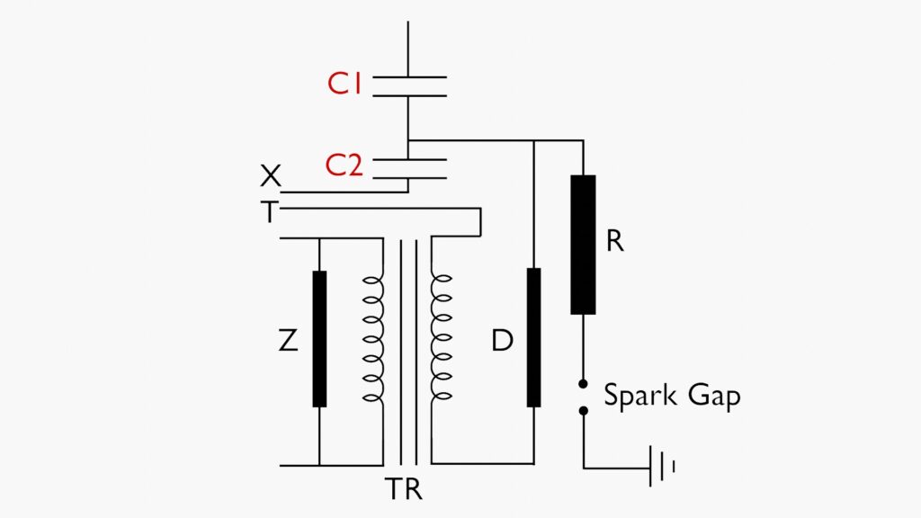
Oil-impregnated paper and aluminum foil form the capacitors () and (). Between these capacitors, a tap is provided to connect to the magnetic voltage transformer (TR). Accordingly, manufacturers fix this point based on the system voltage. In practical design, the magnetic transformer is typically rated for a standard primary voltage of 5, 10, 15, or 20 kV, depending on the burden and accuracy requirements.
Furthermore, a CVT consists of different special auxiliary circuit elements. These include
(i) Compensating inductance coil (D),
(ii) Damping impedance (Z),
(iii) Resistor (R), and
(iv) Spark gap (F).
The compensating inductance coil in series with the primary of the induction transformer compensates the capacitive reactance on the capacitive voltage divider. The damping impedance (Z) across the secondary circuit reduces ferro-resonance. The resistor and spark gap provide necessary protection arrangements.
What is the main purpose of the compensating inductance coil in a CVT?
The most important advantage of the compensating coil in a Capacitor Voltage Transformer (CVT) is its ability to correct the phase angle of the output voltage. A CVT uses a capacitive divider, which introduces phase shifts of divided voltage due to capacitive reactance. The compensating coil provides inductive reactance to compensate for the capacitive reactance. Therefore, the error in the output voltage remains under the limit.
What is the purpose of damping impedance across the secondary circuit of a CVT?
A CVT has inductive circuits as well as capacitive circuits. As a result of the interaction between these capacitive and inductive circuits, along with ferro-resonance in the inductive circuit during a faulty or transient over-voltage condition, nonlinear oscillations may occur on the output voltage. To address this issue, a damping impedance (resistance) (Z) is placed across the secondary circuit to damp these oscillations.
Video on Internal Circuits of CVT