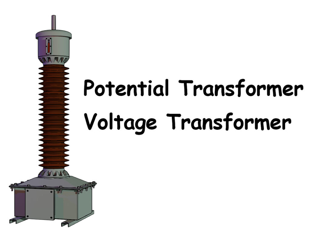
A voltage transformer is a type of instrument transformer. We also call it a potential transformer. It reduces high voltage to a lower and measurable value according to its turns ratio.
We need to measure the voltage in extra-high-voltage (EHV) systems. However, a normal measuring instrument cannot measure such high voltages directly. So, a voltage transformer steps down the voltage to 110 volts or 63.5 volts (110/√3).
We also use it for protection. The transformer copies the voltage disturbance of the system, but in a lower range. This lower voltage goes to the protection relay, which can handle it safely.
For measuring power and energy, devices like wattmeters and watt-hour meters need a voltage input. The secondary of the voltage transformer provides this input.
Working Principle of Potential Transformer
The working principle of a potential transformer, also called a voltage transformer, is similar to that of a power transformer. More precisely, it works on the principle of a two-winding transformer.
We connect the primary winding between the line and the ground. Thus, we apply the phase voltage, which equals the line voltage divided by \( \sqrt3\), across the primary winding. This applied voltage induces an EMF across the secondary winding of the potential transformer. We design the turns ratio of a potential transformer in such a way that, ideally, the secondary winding always gives \( 110/\sqrt3\) volts, which is approximately 63.5 volts. When the secondary delivers 110 volts, we calibrate the voltmeter connected across the secondary terminals to show the full primary voltage.
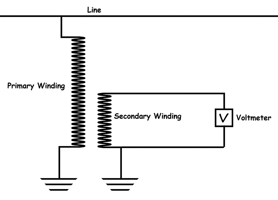
If the primary voltage varies, the PT reproduces the same variation in the secondary voltage but with reduced amplitude. As a result, the voltmeter reflects the actual variation of the primary voltage by receiving the reduced and reproduced secondary voltage from the potential transformer.
Constructional Details of an Inductive Voltage Transformer
The working principle of a voltage transformer is quite similar to that of a step-down power transformer. However, the design of a potential transformer is different from that of a power transformer or a distribution transformer. This is because a voltage transformer serves a different purpose than a power transformer. Now, let us discuss the constructional details of an inductive potential transformer.
Core
Manufacturers normally construct the core of a potential transformer using high-grade cold-rolled grain-oriented silicon steel. Grain orientation reduces hysteresis loss. Laminations further reduce eddy current loss. Manufacturers use an insulating coating on each lamination. This coating insulates one lamination from another and increases the effective resistance of the core. As a result, the eddy current loss reduces significantly. After preparing the core, manufacturers wrap insulating paper around it.
Primary Winding
The primary winding of a voltage transformer consists of several turns of thicker insulated wire. It carries very low current but must withstand high voltage because it connects directly to the high-voltage line. Proper insulation design is essential, since any voltage surge on the line directly hits the primary winding. In high-voltage PTs, manufacturers often use special oil-paper insulation for wrapping the primary winding.
Secondary Winding
The secondary winding has fewer turns than the primary winding. It usually consists of fine copper wire. Since it deals with only a low voltage (about 110 V or lower), the insulation requirement is not as heavy as that of the primary winding. The ends of the secondary winding come out to the secondary terminals in the secondary terminal box. Designers give special importance to insulation between the windings, and also between the windings and the core, to optimize insulation requirements.
Core and Tank
The core and windings are enclosed in a sealed tank. This sealed tank contains the entire core-and-winding assembly. The tank may be filled with insulating material such as oil for cooling and insulation.
Causes of Errors in a Voltage Transformer
Like other instrument transformers, such as current transformers, a potential transformer also has two types of errors: ratio error and phase angle error.
Ratio Error
A voltage transformer or potential transformer steps down the primary voltage to a measurable secondary level, usually 110 volts or 110 divided by √3 volts. However, the secondary voltage is not exactly proportional to the primary voltage. This happens because the transformer circuit has inherent resistance and reactance. The resistance and reactance drops in both the primary and secondary circuits disturb the voltage ratio. In addition, the magnetizing current and the core-loss component of the excitation current also introduce errors.
Phase Angle Error
Due to the magnetizing component and the core-loss component of the excitation current, a slight phase angle error occurs. As a result, there is a small difference between the primary voltage and the secondary voltage in phase relationship.
Vector Diagram of Potential Transformer
The \(V_1\) is the applied voltage across the primary terminals of a PT. Let us consider \(I_0\) represents the excitation current of the PT. This current is the vector sum of the magnetizing current and the core loss current.
Let’s \({I_1}’\) represent the current that the PT actually transforms to the secondary. Whenever we connect a burden across the PT secondary, the secondary current \(I_2\) starts flowing. Obviously, this secondary current reflects as\({I_1}’\) in the primary.
Therefore, the total current entering the primary winding is the vector sum of \(I_0 \) and \({I_1}’\). We draw this total current as \(I_1\). Obviously, this \(I_1\) flows through the primary winding.
Applied Input Voltage
Now, due to this current, there is:
- A resistive drop \(I_1R_1\) (caused by resistance of the primary winding).
- A reactive drop \(jX_1I_1\) (caused by leakage reactance \(X_1\) of the primary winding due to flux leakage).
Thus, the actual induced voltage across the primary winding, \[E_1=V_1−I_1R_1−jX_1I_1\], \(V_1\) is the applied primary voltage. This induced voltage \(E_1\) causes the secondary induced voltage \(E_2\) across the secondary winding.
Obtained Output Voltage
When we connect a burden across the secondary, the secondary current \(I_2\) flows. But the secondary winding itself has its inherent resistance \(R_2\) and leakage reactance \(X_2\). Therefore, there are voltage drops \(I_2R_2\) and \(jX_2I_2\) in the secondary.
So, we can write, the actual voltage that appears across the burden (e.g., voltmeter) connected to the PT secondary terminals as \[V_2=E_2−I_2R_2−jX_2I_2\]
Ratio Error: Hence, the ideal transformation occurs between \(E_1\) and \(E_2\), while in reality we apply \(V_1\) and obtain \(V_2\) at the secondary. Ideally, \[\frac{E_1}{E_2} = \frac{N_1}{N_2}= \text{Turns Ratio}\]But practically, \[\frac{V_1}{V_2} \neq \frac{N_1}{N_2}\] This deviation causes the Ratio Error.
Phase Angle Error: Ideally, the phase angle difference between the primary voltage \(V_1\) and the secondary voltage \(V_2\) should be exactly \(0^o\). In other words, the phase difference between \(V_1\) and reversed \(V_2\) equals \(0^o\). However, due to excitation current components and winding drops, the actual \(180^o\) phase difference appears between \(E_1\) and \(E_2\), not between \(V_1\) and \(V_2\). We refer to the difference between the actual phase angle and the ideal phase angle as the Phase Angle Error, measured in degrees or minutes.