To design the proper grounding systems for transmission line towers, we need to know the soil resistivity. Here, we shall provide a comprehensive guide.
Wenner Four Point Method
We follow the IEEE 81 Standard for soil resistivity measurement for this purpose. We need the following equipment for the measurement.
- Ground resistance tester (Earth tester/megger)
- Four metal electrodes/stakes (usually copper or steel rods)
- Four insulated test leads
- Measuring tape (50-100m)
- Hammer/sledge for driving stakes
- Data recording sheet
Step-by-Step Procedure
Select Test Location: We must choose the measurement of location along the transmission line route. As per IS 3043, these locations must be at least 4km apart along the line.
Set Up Equipment: We first drive 4 electrodes in a straight line along the direction of the line. We space them equally, say at a distance ‘a’. Moreover, we insert the electrodes at a depth of ~15-30 cm in the ground.
Connect Tester: Then, we connect two outer electrodes (C1, C2) to the current terminals. In addition, we connect the inner electrodes (P1, P2) to the potential terminals.
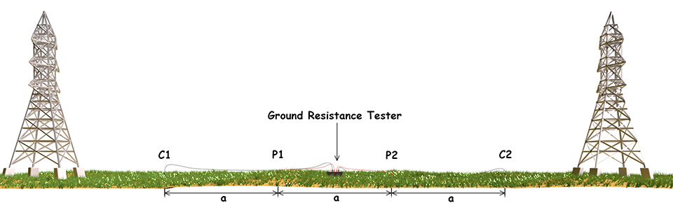
Take Measurements: We begin by taking measurements with a small spacing (a = 1m). The instrument injects a constant direct current through C1. This injected current returns to the instrument through C2. Additionally, the instrument measures the potential drop between P1 and P2. The ratio of measured potential drop to the injected current gives the resistance (R) value. Then, we calculate the resistivity. The formula \(\rho = 2\pi \times a\times R\).
Repeat the Measurements: We repeat the same measurement by increasing the (a) spacing progressively (2m, 3m, 5m, 10m, 15m, 20m). Each spacing probes deeper soil layers.
Test Directions: For transmission lines, we should take the measurements along the direction of the line throughout the length approximately once in every 4 km. This is as per IS – 3043 (2018). Although it is not mandetory but we can take repeat measurements at a 90° angle in the same manner. Because, this helps to identify soil anisotropy.
Calculation Example
Let us consider the spacing (a) of eletrodeds (spikes) is 5m. Here, say the ground resistance tester (earth tester/earth megger) gives the reading the resistance (R) as 50 Ω. The Wenner Formula gives the result as \[\rho = 2\pi\times 5\times 50 = 1,571 \,\Omega – m\]
Then we repeat the measrements and calculations for a = 2m, 10m, 15m, 20m, … as per requirement. Finally, we take average of all the calculated resistivity to obtain the average soil resistivity.
Important Considerations
Environmental Factors: We must avoid the soil resistivity measurement in rainy seanon due to wet soil. Because, the lower resistivity of wet soil can mislead the ultimate measurement. Also, we should measure soil resistivity for a transmission line during dry seasons. The resistivity of dry soil can shows for the worst-case scenario.