What is Insulation Resistance?
Insulation resistance measures how well an insulating material stops leakage current. We measure this blocking ability in Ohms (Ω). Furthermore, good insulation has very high resistance. In contrast, poor insulation allows current to leak. Obviously, this leakage can cause electric shocks, equipment damage, and fire hazards.
Basic Formula of Insulation Resistance
To begin with, we use Ohm’s Law to calculate insulation resistance.\[ R = \frac{V}{I} \]Here,
- ( R ) = Resistance in Ohms (Ω)
- ( V ) = Applied voltage in Volts (V)
- ( I ) = Current in Amperes (A)
For insulation, we write,\[ R_{insulation} = \frac{V_{applied}}{I_{leakage}} \]Hence, the leakage current is very small in good insulation. Therefore, the resistance becomes very high.
Understanding Resistivity
Every material has a property called resistivity. Additionally, we denote it by the Greek letter ( \rho ) (rho). Obviously, the resistivity tells us how much a material opposes current flow. The resistance formula using resistivity is
\[ R = \rho \frac{l}{A} \]Where,
- Resistivity in Ohm-meter (Ω·m) = \( \rho \)
- Length of the material in meters (m) = \( l \)
- Cross-sectional area in square meters (m²) = \( A \)
Obviously, good insulators have very high resistivity values. Conductors have very low resistivity values.
Insulation Resistance for Cable (Cylindrical Shape)
Most electrical cables have cylindrical insulation. The conductor sits in the center. Hence, insulation surrounds it in a circular layer. Let us derive the formula step by step.
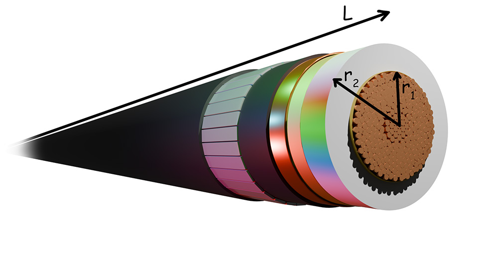
Step 1: Define the Cable Dimensions
- Inner radius (conductor radius) = \( r_1 \)
- Outer radius (insulation outer edge) = \( r_2 \)
- Length of cable = \( L \)
Step 2: Consider Current Flow: Secondly, current flows from the conductor outward through the insulation. At any radius \( r\), the current passes through a cylindrical surface. The area of this surface is \[ A(r) = 2\pi r L \]
Step 3: Calculate Resistance of Thin Shell: Then, we take a very thin shell at radius \( r \) with thickness \( dr\). The resistance of this thin shell is\[ dR = \frac{\rho dr}{2\pi r L} \]
Step 4: Integrate to Find Total Resistance: After that we add up resistances from \( r_1 \) to \( r_2 \) using integration\[R = \int_{r_1}^{r_2} \frac{\rho}{2\pi r L} dr \]\[\Rightarrow R = \frac{\rho}{2\pi L} \int_{r_1}^{r_2} \frac{dr}{r} \]\[\Rightarrow R = \frac{\rho}{2\pi L} [\ln r]_{r_1}^{r_2} \]\[ R = \frac{\rho}{2\pi L} (\ln r_2 – \ln r_1) \]
Final Formula for Cable Insulation
\[ R_{insulation} = \frac{\rho}{2\pi L} \ln\left(\frac{r_2}{r_1}\right) \]This formula helps us calculate insulation resistance for any cable when we know its dimensions and material resistivity.
Insulation Resistance for Flat Insulation
Similarly, sometimes we use flat sheets of insulation. Examples include transformer insulation, capacitor dielectrics, and PCB insulation. For a flat rectangular piece,
- Thickness = d
- Area = A
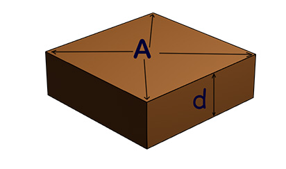
In this case, the current flows straight through from one side to the other. So, we use here the simple formula,\[ R_{insulation} = \rho \frac{d}{A} \]Obviously, A thicker insulation gives higher resistance. On the other hand, A larger area gives lower resistance.
Insulation Resistance for Spherical Shape
Some equipment uses spherical insulation. Examples include high-voltage bushings and certain capacitors. For a sphere
- Inner radius = \( r_1 \)
- Outer radius = \( r_2 \)
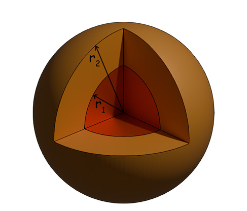
At radius r, current flows through area, \[ A(r) = 4\pi r^2 \] Therefore, resistance of thin shell \[ dR = \frac{\rho dr}{4\pi r^2} \]Then, integrating from \( r_1 \) to \( r_2 \)\[ R = \int_{r_1}^{r_2} \frac{\rho}{4\pi r^2} dr \]\[\Rightarrow R = \frac{\rho}{4\pi} \int_{r_1}^{r_2} \frac{dr}{r^2} \]\[\Rightarrow R = \frac{\rho}{4\pi} \left[-\frac{1}{r}\right]_{r_1}^{r_2} \]\[\Rightarrow R = \frac{\rho}{4\pi} \left(\frac{1}{r_1} – \frac{1}{r_2}\right) \]Hence, the final formula is\[ R_{insulation} = \frac{\rho}{4\pi} \frac{(r_2 – r_1)}{r_1 r_2} \]
How Temperature Affects Insulation Resistance
Temperature plays a very important role. When the temperature increases, the insulation resistance decreases. The mathematical relationship is\[ R_T = R_0 \times e^{-\alpha(T – T_0)} \]Where,
- Resistance at temperature \( T \) =\( R_T \)
- Resistance at reference temperature \( T_0 \) = \( R_0 \)
- Temperature coefficient = \( \alpha \)
- Natural exponential \(2.718…\) = \( e \)
Simple Rule of Thumb for Insulation Resistance
However, for most insulating materials, a simple rule works well. Insulation resistance becomes half for every 10°C rise in temperature. We can write this as \[ R_T = R_0 \times (0.5)^{\frac{T – T_0}{10}} \]For example, at 20°C R is 100 MΩ, at 30°C R is 50 MΩ and at 40°C R is 25 MΩ. This shows why we must always note the temperature during testing.
Types of Leakage Current
When we apply voltage to insulation, different types of current flow through it.
Volume Leakage Current
This current flows through the bulk of the insulation material. We calculate it as\[ I_v = \frac{V}{R_{volume}} \] Therefore, this is the main component we want to measure.
Surface Leakage Current
This current flows along the surface of the solid insulator. Dust, moisture, and dirt on the surface create a path for current.\[ I_s = \frac{V}{R_{surface}} \]We should clean the surface before testing to reduce this current.
Capacitive Charging Current
When we first apply voltage, the insulation acts like a capacitor. It draws charging current.\[ I_c = C \frac{dV}{dt} \]Where
- \( C \) = Capacitance of insulation
- \( \frac{dV}{dt} \) = Rate of voltage change
This current decreases quickly with time. After some time, it becomes almost zero.
Total Current
The total current we measure is\[ I_{total} = I_v + I_s + I_c \]After the capacitive current settles.\[ I_{leakage} = I_v + I_s \]
How Current Changes with Time
When we apply DC voltage to insulation, the current does not become constant immediately. It decreases slowly with time. The current equation is. \[ I(t) = I_{\infty} + I_{absorption} \times e^{-t/\tau} \]Where
- Final steady current = \( I_{\infty} \)
- Initial absorption current = \( I_{absorption} \)
- Time constant = \( \tau \)
- Time elapsed = \( t \)
The measured resistance increases with time. \[ R(t) = \frac{V}{I(t)} \]After long time (when \( t \) is very large):\[ R_{insulation} = \frac{V}{I_{\infty}} \]This is why we must wait for some time before reading the final value during testing.
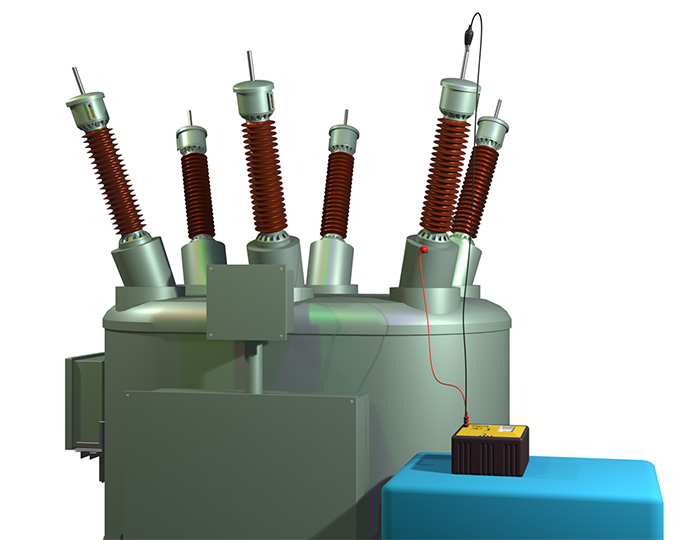
Measuring Insulation Resistance (Megger Test)
We use a special instrument called a Megger or Insulation Tester. This device applies a high DC voltage and measures tiny leakage current.
Test Voltage Selection
We choose the test voltage based on the equipment voltage rating. When the equipment is rated up to 100V, we use 100-250V DC. When the equipment is rated 440-550V: Use 500-1000V DC, and when the equipment is rated above 550V: Use 1000-5000V DC. But never use AC voltage for insulation testing. Always use DC voltage.
Testing Procedure
Firstly, we disconnect the equipment from the power supply. Then we discharge any stored charge by touching it with any earth connection. After that, we clean the insulation surface. Then we connect the Megger leads properly. Normally, we connect the negative lead with the stud or phase terminal and the positive terminal to the other end. Finally, we apply DC test voltage from the Megger and wait for at least 1 minute for stable readings. Then, we record the resistance value and note the ambient temperature. At last, we discharge the equipment again for safety.
Polarization Index
Polarization Index (PI) helps us judge insulation quality. We take two readings
- Reading after 1 minute = \( R_1 \)
- Reading after 10 minutes = \( R_{10} \)
\[ PI = \frac{R_{10}}{R_1} \]
Interpretation
- Good insulation: ( PI > 2 )
- Questionable: ( 1 < PI < 2 )
- Poor insulation: ( PI < 1 )
Good insulation shows increasing resistance with time. This gives PI greater than 2. Damaged insulation shows little change, giving PI close to 1(one).
Minimum Safe Values
Electrical standards specify minimum insulation resistance values. A common rule is\[ R_{min} = \text{Rated Voltage (kV)} + 1 \text{ MΩ} \]For example,
- 440V equipment: ( R_{min} = 0.44 + 1 = 1.44 ) MΩ
- 11 kV equipment: ( R_{min} = 11 + 1 = 12 ) MΩ
For motors and generators at 40°C, another formula applies:\[ R_{min} = \frac{\text{Rated Voltage (V)}}{1000} + 1 \text{ MΩ} \]These are minimum values. Good insulation usually shows much higher values.
Temperature Correction
We must correct measured values to a standard reference temperature (say, it is 40°C). Certainly, this allows fair comparison. The correction formula is\[ R_{40°C} = R_{measured} \times (0.5)^{\frac{T_{measured} – 40}{10}} \]
Example Calculation: Suppose we measure 50 MΩ at 60°C. To correct to 40°C:\[ R_{40°C} = 50 \times (0.5)^{\frac{60 – 40}{10}} \]\[ \Rightarrow R_{40°C} = 50 \times (0.5)^2 \]\[ R_{40°C} = 50 \times 0.25 = 12.5 \text{ MΩ} \]Always correct your readings to standard temperature before comparing with limits.
Power Loss in Insulation
Insulation is not perfect. Therefore, some power always dissipates as heat in the insulation. This is because the leakage current through an insulation can not be made ideally zero. The power loss formula is\[ P = \frac{V^2}{R_{insulation}} = I_{leakage} \times V \]. Obviously, the higher insulation resistance means lower power loss. Hence, high insulation resistance keeps the insulation cooler and increases its life. For example:
- Voltage = 11,000V
- Insulation resistance = 100 MΩ
\[ P = \frac{(11000)^2}{100 \times 10^6} = 1.21 \text{ W} \]This small power loss is acceptable. But if resistance drops to 1 MΩ, power loss becomes 121W, which can overheat the insulation.